Yamaha M2500 Owner's Manual - Page 15
LCR switch is on, LCR switch is off
 |
View all Yamaha M2500 manuals
Add to My Manuals
Save this manual to your list of manuals |
Page 15 highlights
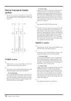
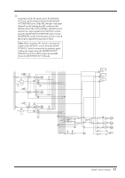
Control panel s GROUP/AUX FLIP switch= AUX ( ) The signals of AUX buses 7-14 will be sent to channels G1/A7-G8/A14 respectively, and will be output individually from the GRP/AUX OUT G1/A7-G8/ A14 jacks. AUX5 0 10 AUX6 0 10 AUX7 0 10 AUX8 PRE 0 10 AUX9 0 10 AUX10 PAN C PAN C L R L R MATRIX ST MATRIX ST MONO MONO LCR LCR CHECK ON CHECK ON ON/EDIT ON/EDIT 10 5 0 5 10 20 30 40 50 60 AFL 10 5 0 5 10 20 30 40 50 60 AFL G1 / A7 G2 / A8 D PAN control This adjusts the pan of the signal that is sent from the G1/A7-G8/A14 section to the STEREO or MONO/C bus. The function of the PAN control will change as follows, depending on the setting of the channel assign switch (5). q When the ST switch is on PAN will adjust the pan of the signal that is sent from each channel to the STEREO L/R bus. q When the LCR switch is on PAN will adjust the pan of the signal that is sent from each channel to the STEREO L/R bus and MONO/C bus. E Channel assign switches These switches assign the post-fader post-PAN signal to the desired bus. • ST (stereo) switch If this switch is on ( ), the post-PAN signal of the output channel will be sent to the STEREO bus. • MONO (monaural) switch If this switch is on ( ), the signal of the output channel will be sent to the MONO/C bus. • LCR switch If this switch is on, the indicator above the switch will light, and the post-PAN signal of the output channel will be sent to the STEREO bus and the MONO/C bus. • MATRIX switch IF this switch is on ( ), the signal of the output channel will be sent to the corresponding MATRIX bus. Note: • The LCR switch takes priority over the ST/ MONO switch. If the LCR switch is on, the post-PAN signal of the G1/A7-G8/A14 section will be sent to the STEREO bus (L/R) and MONO/C bus regardless of the on/off status of the ST/MONO switch. (Refer to response curve diagram 1 on page 4.) • If the LCR switch is off, the ST/MONO switch will function as a conventional channel assign switch. If ST is on, the post-PAN signal of the G1/A7-G8/A14 section will be sent to the ST bus. If the MONO switch is on, the signal of the G1/A7-G8/A14 section will be sent directly to the MONO/C bus. (Refer to response curve diagram 2 on page 4.) 12 M2500-Owner's Manual
-
 1
1 -
2
-
3
-
4
-
5
-
6
-
7
-
8
-
9
-
 10
10 -
 11
11 -
 12
12 -
 13
13 -
 14
14 -
 15
15 -
 16
16 -
 17
17 -
 18
18 -
 19
19 -
 20
20 -
21
-
22
-
23
-
24
-
25
-
26
-
27
-
28
-
29
-
30
-
31
-
32
-
33
-
34
-
35
-
36
-
37
-
38
-
39
-
40
-
41
-
42
-
43
-
44
-
45
-
46
-
47
-
48
-
49
-
50
-
51
-
52
-
53
-
54
-
55
-
56
-
57
-
58
-
59
-
60
-
61
-
62
-
63
-
64
-
65
-
66
-
67
-
68
-
69
-
70
-
71
-
72
-
73
-
74
-
75
-
76
-
77
-
78
-
79
-
80
-
81
-
82
-
83
-
84
-
85
-
86
-
87
-
88
-
89
-
90
-
91
-
92
-
93
-
94
-
95
-
96
-
97
-
98
-
99
-
100
-
101
-
102
-
103
-
104
-
105
-
106
-
107
-
108
-
109
-
110
-
111
-
112
-
113
-
114
-
115
-
116
-
117
-
118
-
119
-
120
-
121
-
122
-
123
-
124
-
125
-
126
-
127
-
128
-
129
-
130
-
131
-
132
-
133
-
134
-
135
-
136
-
137
-
138
-
139
-
140
-
141
-
142
-
143
 |
 |
