Yamaha M2500 Owner's Manual - Page 27
Meter bridge - power supply
 |
View all Yamaha M2500 manuals
Add to My Manuals
Save this manual to your list of manuals |
Page 27 highlights
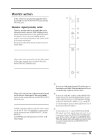
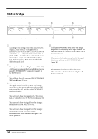
Control panel Meter bridge 1 2 4 20 10 75 PEAK 3 10 3 VU + 1/7 20 10 75 PEAK 3 10 3 VU + 2/8 20 10 7 PEAK 3 10 3 VU + 20 10 75 PEAK 3 10 3 VU + 7/13 20 10 75 PEAK 3 10 3 VU + 8/14 +15V -15V +12V PHANTOM MASTER 20 10 75 PEAK 3 10 3 VU + STEREO L PFL/AFL L 20 10 75 PEAK 3 10 3 VU + MONO/C 20 10 75 PEAK 3 10 3 - VU + STEREO R PFL/AFL R 3 5 A 1/7-8/14 level meters According to the setting of the meter select switches (page 22), these indicate the output levels of MATRIX OUT 1-8, AUX/GRP OUT A7/G1-A14/G8, AUX OUT 1-6, or GRP/AUX OUT G1/A7-G8/A14. (If the AUX 1-6 switch has been selected in the meter select section, meters 7/13 and 8/14 will not function.) Each meter has a PEAK indicator that lights 3 dB before peak level. B +15V/-15V/+12V indicators The respective indicator will light when +15V/-15V/ +12V power is being supplied correctly from the rear panel DC POWER INPUT connector (page 29) to the M2500 mixer. C PHANTOM MASTER indicator This will light when the rear panel PHANTOM MASTER switch (page 29) is on. D STEREO, PFL/AFL level meters The signal shown by each level meter will change depending on the settings of the input channel PFL switches and the AFL switches of the GROUP/AUX master section etc. • PFL/AFL switches= all off The meters will show the output level of the signals that are output from the ST OUT L/R jacks (page 28). • PFL switch= on The meters will show the signal level that is output from the MONITOR INPUT PFL bus. • AFL switch= on (PFL switches= all off) The meters will show the signal level that is output from the MONITOR MASTER AFL bus. Each meter has a PEAK indicator that lights 3 dB before peak level. E MONO/C level meter The signal shown by this level meter will change depending on the settings of the input channel PFL switches and the AFL switches of the GROUP/AUX master section etc. • PFL/AFL switches= all off The meter will show the output level of the signal that is output from the MONO/C OUT jack (page 28). • PFL switch= on • AFL switch= on The MONO/C level meter will not function. This meter has a PEAK indicator that lights 3 dB before peak level. 24 M2500-Owner's Manual
-
 1
1 -
2
-
3
-
4
-
5
-
6
-
7
-
8
-
9
-
10
-
11
-
12
-
13
-
14
-
15
-
16
-
17
-
18
-
19
-
20
-
21
-
 22
22 -
 23
23 -
 24
24 -
 25
25 -
 26
26 -
 27
27 -
 28
28 -
 29
29 -
 30
30 -
 31
31 -
 32
32 -
33
-
34
-
35
-
36
-
37
-
38
-
39
-
40
-
41
-
42
-
43
-
44
-
45
-
46
-
47
-
48
-
49
-
50
-
51
-
52
-
53
-
54
-
55
-
56
-
57
-
58
-
59
-
60
-
61
-
62
-
63
-
64
-
65
-
66
-
67
-
68
-
69
-
70
-
71
-
72
-
73
-
74
-
75
-
76
-
77
-
78
-
79
-
80
-
81
-
82
-
83
-
84
-
85
-
86
-
87
-
88
-
89
-
90
-
91
-
92
-
93
-
94
-
95
-
96
-
97
-
98
-
99
-
100
-
101
-
102
-
103
-
104
-
105
-
106
-
107
-
108
-
109
-
110
-
111
-
112
-
113
-
114
-
115
-
116
-
117
-
118
-
119
-
120
-
121
-
122
-
123
-
124
-
125
-
126
-
127
-
128
-
129
-
130
-
131
-
132
-
133
-
134
-
135
-
136
-
137
-
138
-
139
-
140
-
141
-
142
-
143
 |
 |
