Yamaha M2500 Owner's Manual - Page 23
Dl+r Elevel Fon Gphones Hphones
 |
View all Yamaha M2500 manuals
Add to My Manuals
Save this manual to your list of manuals |
Page 23 highlights
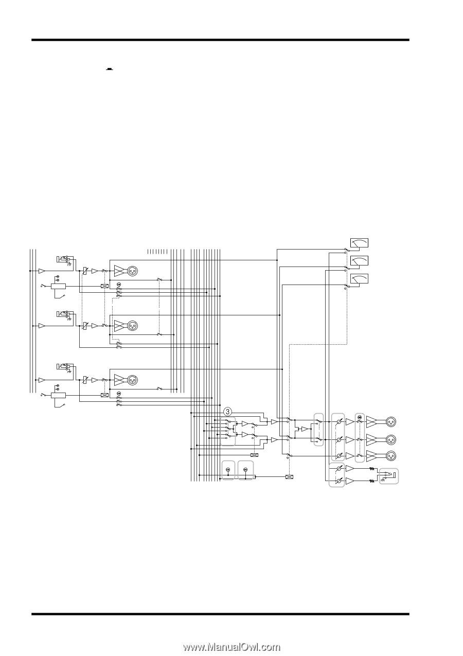
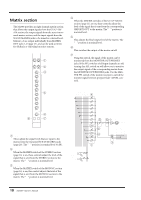
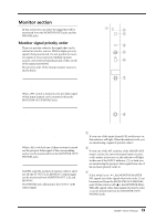
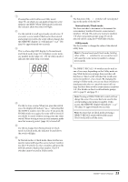
Control panel D L+R switch If this switch is on ( ), the monitor signal sent to the MONITOR OUT/PHONES jacks will be mixed to monaural. E LEVEL control This adjusts the final output level from the MONITOR OUT jacks (L, R, MONO/C). It does not affect the signal that is output from the PHONES jack. The "v" position is nominal level. F ON switch This is an on/off switch for the signal that is output from the MONITOR OUT jacks (L, R, MONO/C). If this is on, the indicator above the switch will light. This switch does not affect the signal that is output from the PHONES jack. G PHONES (headphone) control This adjusts the level of the signal that is output from the PHONES jack. It does not affect the signal that is output from the MONITOR OUT jacks. The "v" position is nominal level. H PHONES jack A set of monitoring headphones can be connected here. STEREO MONO/C G1/A7 G2/A8 G3/A9 G4/A10 G5/A11 G6/A12 G7/A13 G8/A14 STEREO MONO/C SUB IN MONO ST ON MONO ST MONO ST ON LR INSERT I/O 0dB ST L CHECK ON Control ON/EDIT from CPU INSERT I/O 0dB ST R MATRIX MONITOR INPUT MASTER (PFL) PFL AFL LR L R LR LR LR ST OUT +4dB L AFL ON MATRIX ST OUT +4dB R INSERT I/O 0dB MONO/C CHECK ON Control ON/EDIT from CPU +4dB MONO/C MATRIX AFL MASTER PFL INPUT MASTER 12 45 6 L+R LEVEL ON PHONES 7 L MONITOR OUT +4dB R MONO/C 8 20 M2500-Owner's Manual
-
 1
1 -
2
-
3
-
4
-
5
-
6
-
7
-
8
-
9
-
10
-
11
-
12
-
13
-
14
-
15
-
16
-
17
-
 18
18 -
 19
19 -
 20
20 -
 21
21 -
 22
22 -
 23
23 -
 24
24 -
 25
25 -
 26
26 -
 27
27 -
 28
28 -
29
-
30
-
31
-
32
-
33
-
34
-
35
-
36
-
37
-
38
-
39
-
40
-
41
-
42
-
43
-
44
-
45
-
46
-
47
-
48
-
49
-
50
-
51
-
52
-
53
-
54
-
55
-
56
-
57
-
58
-
59
-
60
-
61
-
62
-
63
-
64
-
65
-
66
-
67
-
68
-
69
-
70
-
71
-
72
-
73
-
74
-
75
-
76
-
77
-
78
-
79
-
80
-
81
-
82
-
83
-
84
-
85
-
86
-
87
-
88
-
89
-
90
-
91
-
92
-
93
-
94
-
95
-
96
-
97
-
98
-
99
-
100
-
101
-
102
-
103
-
104
-
105
-
106
-
107
-
108
-
109
-
110
-
111
-
112
-
113
-
114
-
115
-
116
-
117
-
118
-
119
-
120
-
121
-
122
-
123
-
124
-
125
-
126
-
127
-
128
-
129
-
130
-
131
-
132
-
133
-
134
-
135
-
136
-
137
-
138
-
139
-
140
-
141
-
142
-
143
 |
 |