Yamaha M2500 Owner's Manual - Page 21
Matrix
 |
View all Yamaha M2500 manuals
Add to My Manuals
Save this manual to your list of manuals |
Page 21 highlights
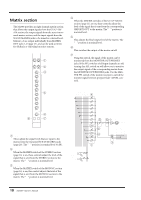
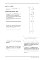
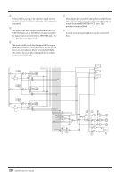
Control panel Matrix section The M2500 provides an eight channel matrix section that allows the output signals from the G1/A7-G8/ A14 section, the output signals from the stereo/monaural master section, and the input signals from the SUB IN MATRIX jacks to be mixed at a desired level. Matrix 1-8 are output individually from MATRIX OUT jacks 1-8 (page 27), and can be used as mixes for foldback or individual monitor systems. 0 0 L SUB IN R 0 0 L ST R 0 MONO/C 0 G1 / A7 0 G2 / A8 0 G3 / A9 0 G4 / A10 0 G5 / A11 0 G6 / A12 0 G7 / A13 0 G8 / A14 6 0 10 LEVEL ON AFL MATRIX 1 1 2 3 4 5 7 A SUB IN L/R control These adjust the signal levels that are input to the matrix from the rear panel SUB IN MATRIX jacks (page 28). The "v" position is nominal level (0 dB). B ST L/R controls When the MATRIX switch of the STEREO section (page 16) is on, these controls adjust the level of the signal that is sent from the STEREO section to the matrix. The "v" position is nominal level. C MONO/C control When the MATRIX switch of the MONO/C section (page 16) is on, this control adjusts the level of the signal that is sent from the MONO/C section to the matrix. The "v" position is nominal level. D G1/A7-G8/A14 controls When the MATRIX switches of the G1/A7-G8/A14 section (page 11) are on, these controls adjust the level of the signal that is sent from the corresponding GRP/AUX OUT to the matrix. The "v" position is nominal level. E LEVEL control This adjusts the final output level of the matrix. The "v" position is nominal level. F ON switch This switches the output of the matrix on/off. G AFL switch Using this switch, the signal of the matrix can be monitored from the MONITOR OUT/PHONES jacks. If the PFL switches of all input channels are off, turning this AFL switch on will allow you to monitor the output signal of the corresponding matrix from the MONITOR OUT/PHONES jacks. Use the MASTER PFL switch of the monitor section to switch the monitor signal between pre/post-fader (LEVEL control). G1/A7 G2/A8 G3/A9 G4/A10 G5/A11 G6/A12 G7/A13 G8/A14 STEREO MONO/C SUB IN MATRIX 4 L R L R G1/A7 G2/A8 G7/A9 G7/A10 G7/A11 G7/A12 G7/A13 G8/A14 ST L ST R MONO/C SUB IN L SUB IN R 1 5 LEVEL 2 3 6 ON to METER MATRIX OUT +4dB 1-8 MONITOR INPUT MASTER (PFL) PFL AFL LR LR LR AFL 7 L SUB IN +4dB MATRIX R MONO ST ON MONO ST MONO ST ON 18 M2500-Owner's Manual
-
 1
1 -
2
-
3
-
4
-
5
-
6
-
7
-
8
-
9
-
10
-
11
-
12
-
13
-
14
-
15
-
 16
16 -
 17
17 -
 18
18 -
 19
19 -
 20
20 -
 21
21 -
 22
22 -
 23
23 -
 24
24 -
 25
25 -
 26
26 -
27
-
28
-
29
-
30
-
31
-
32
-
33
-
34
-
35
-
36
-
37
-
38
-
39
-
40
-
41
-
42
-
43
-
44
-
45
-
46
-
47
-
48
-
49
-
50
-
51
-
52
-
53
-
54
-
55
-
56
-
57
-
58
-
59
-
60
-
61
-
62
-
63
-
64
-
65
-
66
-
67
-
68
-
69
-
70
-
71
-
72
-
73
-
74
-
75
-
76
-
77
-
78
-
79
-
80
-
81
-
82
-
83
-
84
-
85
-
86
-
87
-
88
-
89
-
90
-
91
-
92
-
93
-
94
-
95
-
96
-
97
-
98
-
99
-
100
-
101
-
102
-
103
-
104
-
105
-
106
-
107
-
108
-
109
-
110
-
111
-
112
-
113
-
114
-
115
-
116
-
117
-
118
-
119
-
120
-
121
-
122
-
123
-
124
-
125
-
126
-
127
-
128
-
129
-
130
-
131
-
132
-
133
-
134
-
135
-
136
-
137
-
138
-
139
-
140
-
141
-
142
-
143
 |
 |
