Yamaha M2500 Owner's Manual - Page 22
Monitor
 |
View all Yamaha M2500 manuals
Add to My Manuals
Save this manual to your list of manuals |
Page 22 highlights
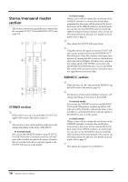
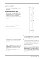
Control panel Monitor section In this section you can select the signal that will be monitored from the MONITOR OUT jacks and the PHONES jacks. Monitor signal priority order There is a priority order for the signals that can be selected as monitor sources. While a higher priority signal is being monitored, it is not possible to monitor signals of a lower priority. Multiple monitor sources can be selected simultaneously if they are all of the same priority level. The priority order of the various monitor sources is shown below. Priority order 1 • Pre-fader signal of a monaural input channel (PFL switch) • Pre-fader signal of a stereo input channel (PFL switch) When a PFL switch is turned on, the pre-fader signal of that input channel can be monitored from the MONITOR OUT/PHONES jacks. Priority order 2 • Pre/post-fader signals of the AUX 1-6 section (AFL switch) • Pre/post-fader signals of the A7/G1-A14/G8 section (AFL switch) • Pre/post-fader signals of the G1/A7-G8/A14 section (AFL switch) • Pre/post-fader signals of the STEREO section (AFL switch) • Pre/post-fader signals of the MONO/C section (AFL switch) • Pre/post-fader signals of the matrix section (AFL switch) When a AFL switch of one of these sections is turned on, the pre/post-fader signal of the corresponding section can be monitored from the MONITOR OUT/ PHONES jacks. Priority order 3 • ST OUT (L, R, MONO/C) output signals If all PFL and AFL switches of priority orders 1 and 2 are off, the ST OUT (L, R, MONO/C) output signal can be monitored from MONITOR OUT L, R, and MONO/C. The PHONES jack will monitor the ST OUT (L/R) output signal. 1 INPUT MASTER MASTER PFL 2 3 L+R 0 10 LEVEL ON 4 5 6 MONITOR 0 10 PHONES 7 8 PHONES A INPUT indicator If even one of the input channel PFL switches are on, this indicator will light. When this indicator is lit, you are monitoring a signal of priority order 1. B MASTER indicator If even one of the AFL switches of the GROUP/AUX master section, the stereo/monaural master section, or the matrix section are on, this indicator will light. In this case if the INPUT indicator (1) is dark, you are monitoring the pre/post-fader signal from one of the sections (priority order 2). C MASTER PFL switch If this switch is on ( ), the MONITOR MASTER PFL signals (pre-fader signals of priority order 2) can be monitored from the MONITOR OUT/PHONES jacks. If this switch is off ( ), the MONITOR MASTER AFL signals (after-fader signals of priority order 2) can be monitored from the MONITOR OUT/ PHONES jacks. 19 M2500-Owner's Manual
-
 1
1 -
2
-
3
-
4
-
5
-
6
-
7
-
8
-
9
-
10
-
11
-
12
-
13
-
14
-
15
-
16
-
 17
17 -
 18
18 -
 19
19 -
 20
20 -
 21
21 -
 22
22 -
 23
23 -
 24
24 -
 25
25 -
 26
26 -
 27
27 -
28
-
29
-
30
-
31
-
32
-
33
-
34
-
35
-
36
-
37
-
38
-
39
-
40
-
41
-
42
-
43
-
44
-
45
-
46
-
47
-
48
-
49
-
50
-
51
-
52
-
53
-
54
-
55
-
56
-
57
-
58
-
59
-
60
-
61
-
62
-
63
-
64
-
65
-
66
-
67
-
68
-
69
-
70
-
71
-
72
-
73
-
74
-
75
-
76
-
77
-
78
-
79
-
80
-
81
-
82
-
83
-
84
-
85
-
86
-
87
-
88
-
89
-
90
-
91
-
92
-
93
-
94
-
95
-
96
-
97
-
98
-
99
-
100
-
101
-
102
-
103
-
104
-
105
-
106
-
107
-
108
-
109
-
110
-
111
-
112
-
113
-
114
-
115
-
116
-
117
-
118
-
119
-
120
-
121
-
122
-
123
-
124
-
125
-
126
-
127
-
128
-
129
-
130
-
131
-
132
-
133
-
134
-
135
-
136
-
137
-
138
-
139
-
140
-
141
-
142
-
143
 |
 |
