Yamaha M2500 Owner's Manual - Page 24
Talkback/oscillator
 |
View all Yamaha M2500 manuals
Add to My Manuals
Save this manual to your list of manuals |
Page 24 highlights
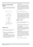
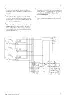
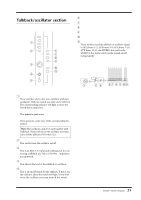
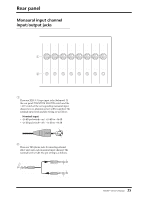
Talkback/oscillator section 1 PINK 10kHz 1kHz 2 100Hz ON OSCILLATOR AUX1-2 AUX3-6 AUX7-10 3 AUX11-14 MIC ST 4 0 10 TB/OSC MONO/C 5 ON TALKBACK 6 7 8 9 J K Control panel F AUX 1-2 switch G AUX 3-6 switch H AUX 7-10 switch I AUX 11-14 switch J ST switch K MONO/C switch These switches send the talkback or oscillator signal to AUX buses 1-2, AUX buses 3-6, AUX buses 7-10, AUX buses 11-14, the STEREO bus, and/or the MONO/C bus. Each switch can be turned on/off independently. STEREO MONO/C MIC 3 AUX 1 3 5 7 9 11 13 LR 2 4 6 8 10 12 14 from CPU ON TB/OSC 54 67 8 9 JK A OSCILLATOR select switches These switches select a test tone oscillator, and start oscillation. Only one switch at a time can be selected. The corresponding indicator will light to show the switch that is turned on. • PINK switch This generates pink noise. • 10 kHz/1 kHz/100 Hz switches These generate a sine wave of the corresponding frequency. Note: The oscillator cannot be used together with talkback. If you wish to use the oscillator, you must turn off the talkback ON switch (5). B OSCILLATOR ON switch This switch turns the oscillator on/off. C MIC jack This is an XLR-3-31 input jack (unbalanced) for connecting a talkback mic. Mics of 50-600Ω impedance are supported. D TB/OSC control This adjusts the level of the talkback or oscillator. E ON switch This is an on/off switch for the talkback. If this is on, the indicator above the switch will light. If you wish to use the oscillator, you must turn off this switch. 21 M2500-Owner's Manual
-
 1
1 -
2
-
3
-
4
-
5
-
6
-
7
-
8
-
9
-
10
-
11
-
12
-
13
-
14
-
15
-
16
-
17
-
18
-
 19
19 -
 20
20 -
 21
21 -
 22
22 -
 23
23 -
 24
24 -
 25
25 -
 26
26 -
 27
27 -
 28
28 -
 29
29 -
30
-
31
-
32
-
33
-
34
-
35
-
36
-
37
-
38
-
39
-
40
-
41
-
42
-
43
-
44
-
45
-
46
-
47
-
48
-
49
-
50
-
51
-
52
-
53
-
54
-
55
-
56
-
57
-
58
-
59
-
60
-
61
-
62
-
63
-
64
-
65
-
66
-
67
-
68
-
69
-
70
-
71
-
72
-
73
-
74
-
75
-
76
-
77
-
78
-
79
-
80
-
81
-
82
-
83
-
84
-
85
-
86
-
87
-
88
-
89
-
90
-
91
-
92
-
93
-
94
-
95
-
96
-
97
-
98
-
99
-
100
-
101
-
102
-
103
-
104
-
105
-
106
-
107
-
108
-
109
-
110
-
111
-
112
-
113
-
114
-
115
-
116
-
117
-
118
-
119
-
120
-
121
-
122
-
123
-
124
-
125
-
126
-
127
-
128
-
129
-
130
-
131
-
132
-
133
-
134
-
135
-
136
-
137
-
138
-
139
-
140
-
141
-
142
-
143
 |
 |
