ZyXEL Elite 2864 User Guide - Page 207
ZyXEL Elite 2864 Manual
 |
View all ZyXEL Elite 2864 manuals
Add to My Manuals
Save this manual to your list of manuals |
Page 207 highlights
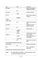
Chapter 18 DIAGNOSTICS The 2864 series modems provide several diagnostic capabilities: • Power-on Self-Test • Analog Loopback Test • Analog Loopback with Self-Test • Local Digital Loopback Test • Remote Digital Loopback Test • Remote Digital Loopback with Self-Test • Line Condition Status Display • Re-transmission Indicator • Throughput Display • Link Status Report • Modem Reset All these tests apply to the asynchronous or synchronous, error controlled or nonerror controlled, data compression enabled or disabled data mode. You can use these capabilities to verify the line condition and the modem's functioning and performance, and to locate the source of a communication problem. Power-on Self-test At each power-up or upon a reset command from the panel, the modem will test the ROM code checksum, system RAM memory, DSP code checksum, DSP RAM memory, EEPROM, digital circuits, and the analog circuit calibrations. On the LCD model, the LCD panel will display the results of the power-on self-test: 0 SYSTEM TESTING.... 1 ROM TEST FAIL.... 2 RAM TEST FAIL.... Self-test indicator. If no error occurs, this message will last until the end of the test. ROM code checksum error. System RAM fails. 18-1
-
 1
1 -
2
-
3
-
4
-
5
-
6
-
7
-
8
-
9
-
10
-
11
-
12
-
13
-
14
-
15
-
16
-
17
-
18
-
19
-
20
-
21
-
22
-
23
-
24
-
25
-
26
-
27
-
28
-
29
-
30
-
31
-
32
-
33
-
34
-
35
-
36
-
37
-
38
-
39
-
40
-
41
-
42
-
43
-
44
-
45
-
46
-
47
-
48
-
49
-
50
-
51
-
52
-
53
-
54
-
55
-
56
-
57
-
58
-
59
-
60
-
61
-
62
-
63
-
64
-
65
-
66
-
67
-
68
-
69
-
70
-
71
-
72
-
73
-
74
-
75
-
76
-
77
-
78
-
79
-
80
-
81
-
82
-
83
-
84
-
85
-
86
-
87
-
88
-
89
-
90
-
91
-
92
-
93
-
94
-
95
-
96
-
97
-
98
-
99
-
100
-
101
-
102
-
103
-
104
-
105
-
106
-
107
-
108
-
109
-
110
-
111
-
112
-
113
-
114
-
115
-
116
-
117
-
118
-
119
-
120
-
121
-
122
-
123
-
124
-
125
-
126
-
127
-
128
-
129
-
130
-
131
-
132
-
133
-
134
-
135
-
136
-
137
-
138
-
139
-
140
-
141
-
142
-
143
-
144
-
145
-
146
-
147
-
148
-
149
-
150
-
151
-
152
-
153
-
154
-
155
-
156
-
157
-
158
-
159
-
160
-
161
-
162
-
163
-
164
-
165
-
166
-
167
-
168
-
169
-
170
-
171
-
172
-
173
-
174
-
175
-
176
-
177
-
178
-
179
-
180
-
181
-
182
-
183
-
184
-
185
-
186
-
187
-
188
-
189
-
190
-
191
-
192
-
193
-
194
-
195
-
196
-
197
-
198
-
199
-
200
-
201
-
 202
202 -
 203
203 -
 204
204 -
 205
205 -
 206
206 -
 207
207 -
 208
208 -
 209
209 -
 210
210 -
 211
211 -
 212
212 -
213
-
214
-
215
-
216
-
217
-
218
-
219
-
220
-
221
-
222
-
223
-
224
-
225
-
226
-
227
-
228
-
229
-
230
-
231
-
232
-
233
-
234
-
235
-
236
-
237
-
238
-
239
-
240
-
241
-
242
-
243
-
244
-
245
-
246
-
247
-
248
-
249
-
250
-
251
-
252
-
253
-
254
-
255
-
256
-
257
-
258
-
259
-
260
-
261
-
262
-
263
-
264
-
265
-
266
-
267
 |
 |
