ZyXEL Elite 2864 User Guide - Page 41
Connecting the Elite 2864
 |
View all ZyXEL Elite 2864 manuals
Add to My Manuals
Save this manual to your list of manuals |
Page 41 highlights
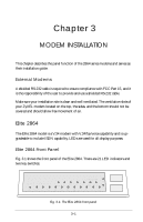
The following table explains the connectors on the rear panel: POWER JACK PARALLEL SERIAL LINE PHONE Input terminal for power adapter. There is no power switch on the modem.The power switch on the power adapter will turn off the power adapter and shut off power to the modem. Always turn off the power adapter before connecting or disconnecting power. For additional safety against possible damage, don't turn on the power with the parallel port connected to a piece of equipment which is under power. Parallel port DB25 male connector for connection to a PC's parallel port or a printer's Centronics compatible port. Serial port DB25 female connector for connection to the serial port of a DTE (computer/terminal). Dial-up line RJ11 terminal jack; for connection to a 2-wire dial-up line on the wall jack. RJ11 terminal jack; for connection to a telephone set. Connecting the Elite 2864 Power Connection Connect the power plug from the adapter to the power jack. Connect one end of the power cord to the power adapter and plug the other end into an electrical outlet. When you connect your 2864 to the power line, make sure you only use the ZyXEL power adapter that is supplied with this unit. Use of another adapter may not allow your modem to operate and could result in serious damage to the unit. This adapter is rated for direct connection to an AC power outlet. Turn off the power on both the computer and the modem before making connections. Then connect the modem according to the rear panel labels. Warning: Always turn off the power switch on the power adapter before connecting to the modem power jack. Never plug or unplug modem's power jack with the power adapter turned on as this may damage the modem. Computer and Printer Connection The modem has both a parallel port and a serial port connector. You can connect the serial port connector to your computer's serial port or connect the parallel port connector to your PC's bidirectional parallel port or you can connect both ports to your PC's serial and parallel port. You can also connect the serial port to your PC's serial port, and the parallel port to a laser printer. If you have the modem set up for auto 3-5
-
 1
1 -
2
-
3
-
4
-
5
-
6
-
7
-
8
-
9
-
10
-
11
-
12
-
13
-
14
-
15
-
16
-
17
-
18
-
19
-
20
-
21
-
22
-
23
-
24
-
25
-
26
-
27
-
28
-
29
-
30
-
31
-
32
-
33
-
34
-
35
-
 36
36 -
 37
37 -
 38
38 -
 39
39 -
 40
40 -
 41
41 -
 42
42 -
 43
43 -
 44
44 -
 45
45 -
 46
46 -
47
-
48
-
49
-
50
-
51
-
52
-
53
-
54
-
55
-
56
-
57
-
58
-
59
-
60
-
61
-
62
-
63
-
64
-
65
-
66
-
67
-
68
-
69
-
70
-
71
-
72
-
73
-
74
-
75
-
76
-
77
-
78
-
79
-
80
-
81
-
82
-
83
-
84
-
85
-
86
-
87
-
88
-
89
-
90
-
91
-
92
-
93
-
94
-
95
-
96
-
97
-
98
-
99
-
100
-
101
-
102
-
103
-
104
-
105
-
106
-
107
-
108
-
109
-
110
-
111
-
112
-
113
-
114
-
115
-
116
-
117
-
118
-
119
-
120
-
121
-
122
-
123
-
124
-
125
-
126
-
127
-
128
-
129
-
130
-
131
-
132
-
133
-
134
-
135
-
136
-
137
-
138
-
139
-
140
-
141
-
142
-
143
-
144
-
145
-
146
-
147
-
148
-
149
-
150
-
151
-
152
-
153
-
154
-
155
-
156
-
157
-
158
-
159
-
160
-
161
-
162
-
163
-
164
-
165
-
166
-
167
-
168
-
169
-
170
-
171
-
172
-
173
-
174
-
175
-
176
-
177
-
178
-
179
-
180
-
181
-
182
-
183
-
184
-
185
-
186
-
187
-
188
-
189
-
190
-
191
-
192
-
193
-
194
-
195
-
196
-
197
-
198
-
199
-
200
-
201
-
202
-
203
-
204
-
205
-
206
-
207
-
208
-
209
-
210
-
211
-
212
-
213
-
214
-
215
-
216
-
217
-
218
-
219
-
220
-
221
-
222
-
223
-
224
-
225
-
226
-
227
-
228
-
229
-
230
-
231
-
232
-
233
-
234
-
235
-
236
-
237
-
238
-
239
-
240
-
241
-
242
-
243
-
244
-
245
-
246
-
247
-
248
-
249
-
250
-
251
-
252
-
253
-
254
-
255
-
256
-
257
-
258
-
259
-
260
-
261
-
262
-
263
-
264
-
265
-
266
-
267
 |
 |
