ZyXEL Elite 2864 User Guide - Page 49
Connecting the Omni 288S, Turning on the Omni 288P or Omni 288S
 |
View all ZyXEL Elite 2864 manuals
Add to My Manuals
Save this manual to your list of manuals |
Page 49 highlights
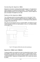
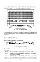
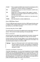
If the modem's parallel port is always connected to a laser printer for fax printing, a computer/terminal can connect to the modem's AUX RS232 serial port for issuing AT commands and reception of responses. This is good for configuration and monitoring operation without disconnecting the laser printer. This AUX RS232 serial port is intended only for AT command and response's transmission; it is not intended for DTE data transmission. Auto speed detection is not supported on this AUX RS232 port. Only the speeds 38400 bps and 19200 bps are supported on the AUX serial port, 38400 bps being the default speed. The asynchronous character format accepted on the AUX RS232 port is 8N1 (8 data bits, no parity, one stop bit). A RJ45 to DB25F connector adapter is needed to convert the RJ45 AUX RS232 port to a normal DCE DB25 female serial port connector. The following table lists the conversion connections: Signal Name TXD RXD RTS CTS GND DSR, CD, DTR Pin No. on DB25F 2 3 4 5 7 6, 8, 20 tied together Pin No. on AUX RJ45 1 8 2 7 3 and 6 - Phone Line Connection Use the telephone cable supplied to connect the modem's LINE jack to the telephone line wall jack. You can also connect a telephone set to the modem's PHONE jack in case you need the telephone for voice communication. A telephone set is not needed for the modem's data, fax, and voice mail communication. The telephone set may also be used to record or to playback voice messages. Connecting the Omni 288S Please refer to the above description for connecting the Omni 288P. The descriptions for the power and phone line connection also apply to the Omni 288S. The descriptions for connection to a computer or a printer through the parallel port do not apply, because the Omni 288S has a serial port for connection to a computer/terminal's serial port only. There is no possibility to connect to a printer by parallel port. Turning on the Omni 288P or Omni 288S Turn on the power switch on the modem to turn on the modem. The modem will do a self-test each time it is turned on. The SQ LED will flash if the power-on selftest fails. For a more detailed description of the diagnostic tests, please refer to chapter 18 (DIAGNOSTICS). 3-13
-
 1
1 -
2
-
3
-
4
-
5
-
6
-
7
-
8
-
9
-
10
-
11
-
12
-
13
-
14
-
15
-
16
-
17
-
18
-
19
-
20
-
21
-
22
-
23
-
24
-
25
-
26
-
27
-
28
-
29
-
30
-
31
-
32
-
33
-
34
-
35
-
36
-
37
-
38
-
39
-
40
-
41
-
42
-
43
-
 44
44 -
 45
45 -
 46
46 -
 47
47 -
 48
48 -
 49
49 -
 50
50 -
 51
51 -
 52
52 -
 53
53 -
 54
54 -
55
-
56
-
57
-
58
-
59
-
60
-
61
-
62
-
63
-
64
-
65
-
66
-
67
-
68
-
69
-
70
-
71
-
72
-
73
-
74
-
75
-
76
-
77
-
78
-
79
-
80
-
81
-
82
-
83
-
84
-
85
-
86
-
87
-
88
-
89
-
90
-
91
-
92
-
93
-
94
-
95
-
96
-
97
-
98
-
99
-
100
-
101
-
102
-
103
-
104
-
105
-
106
-
107
-
108
-
109
-
110
-
111
-
112
-
113
-
114
-
115
-
116
-
117
-
118
-
119
-
120
-
121
-
122
-
123
-
124
-
125
-
126
-
127
-
128
-
129
-
130
-
131
-
132
-
133
-
134
-
135
-
136
-
137
-
138
-
139
-
140
-
141
-
142
-
143
-
144
-
145
-
146
-
147
-
148
-
149
-
150
-
151
-
152
-
153
-
154
-
155
-
156
-
157
-
158
-
159
-
160
-
161
-
162
-
163
-
164
-
165
-
166
-
167
-
168
-
169
-
170
-
171
-
172
-
173
-
174
-
175
-
176
-
177
-
178
-
179
-
180
-
181
-
182
-
183
-
184
-
185
-
186
-
187
-
188
-
189
-
190
-
191
-
192
-
193
-
194
-
195
-
196
-
197
-
198
-
199
-
200
-
201
-
202
-
203
-
204
-
205
-
206
-
207
-
208
-
209
-
210
-
211
-
212
-
213
-
214
-
215
-
216
-
217
-
218
-
219
-
220
-
221
-
222
-
223
-
224
-
225
-
226
-
227
-
228
-
229
-
230
-
231
-
232
-
233
-
234
-
235
-
236
-
237
-
238
-
239
-
240
-
241
-
242
-
243
-
244
-
245
-
246
-
247
-
248
-
249
-
250
-
251
-
252
-
253
-
254
-
255
-
256
-
257
-
258
-
259
-
260
-
261
-
262
-
263
-
264
-
265
-
266
-
267
 |
 |
