ZyXEL Elite 2864 User Guide - Page 42
Elite 2864L
 |
View all ZyXEL Elite 2864 manuals
Add to My Manuals
Save this manual to your list of manuals |
Page 42 highlights
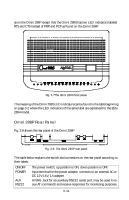
fax receiving and printing, you only need a parallel port connection to a printer. Though you may have both ports connected, only one port is active at any time. If the parallel port is active, it is either in PC communication mode (PCP) or printer driving mode (PRP). Warning: Never try to connect a parallel port to a serial port, it may damage electronic circuits on both ports. They use different voltage levels. A 25-pin male to female shielded RS-232 cable can be used to connect the modem's serial port (female DB25) to a computer's regular RS232 serial port connector (male DB25). If you have an AT type 9-pin serial port connector on your PC, a 9-pin female to 25-pin male cable adapter is needed. If you have other types of serial port connectors, like Apple Macintosh's DIN-8, you need a special adapter cable for it. By reversing the 25-pin RS232 cable it can also be used for connecting the modem's parallel port (male DB25) to a PC's parallel port (female DB25). Refer to chapter 21 for information on high-speed PC-modem communication. The standard PC printer cable will connect a PC's female DB25 parallel port connector to a printer's Centronics 36-pin D-shell connector. You will need a female DB25 to female DB25 gender converter together with a normal PC printer cable to connect the modem's male DB25 parallel port connector to the printer. Phone Line Connection Use the telephone cable supplied to connect the modem's LINE jack to the telephone line wall jack. You can also connect a telephone set to the modem's PHONE jack in case you need the telephone for voice communication. A telephone set is not needed for the modem's data, fax, and voice mail communication. The telephone set may also be used to record or to playback voice messages. Turning on the Elite 2864 Turn on the power switch on the power adapter to turn on the modem. The modem will do a self-test each time it is turned on. The TST LED indicator will be on during the power-on self-test and off after the test if it is OK. The SQ LED flashes if the test fails. For a more detailed description of these diagnostic tests, please refer to chapter 18 (DIAGNOSTICS). Elite 2864L The Elite 2864L model is the model with 2/4-wire leased line support. All other features are the same as those of the Elite 2864 model. Please refer to the description for the Elite 2864, it also applies to the Elite 2864L model. In the following, we will describe the points in which the models differ. 3-6
-
 1
1 -
2
-
3
-
4
-
5
-
6
-
7
-
8
-
9
-
10
-
11
-
12
-
13
-
14
-
15
-
16
-
17
-
18
-
19
-
20
-
21
-
22
-
23
-
24
-
25
-
26
-
27
-
28
-
29
-
30
-
31
-
32
-
33
-
34
-
35
-
36
-
 37
37 -
 38
38 -
 39
39 -
 40
40 -
 41
41 -
 42
42 -
 43
43 -
 44
44 -
 45
45 -
 46
46 -
 47
47 -
48
-
49
-
50
-
51
-
52
-
53
-
54
-
55
-
56
-
57
-
58
-
59
-
60
-
61
-
62
-
63
-
64
-
65
-
66
-
67
-
68
-
69
-
70
-
71
-
72
-
73
-
74
-
75
-
76
-
77
-
78
-
79
-
80
-
81
-
82
-
83
-
84
-
85
-
86
-
87
-
88
-
89
-
90
-
91
-
92
-
93
-
94
-
95
-
96
-
97
-
98
-
99
-
100
-
101
-
102
-
103
-
104
-
105
-
106
-
107
-
108
-
109
-
110
-
111
-
112
-
113
-
114
-
115
-
116
-
117
-
118
-
119
-
120
-
121
-
122
-
123
-
124
-
125
-
126
-
127
-
128
-
129
-
130
-
131
-
132
-
133
-
134
-
135
-
136
-
137
-
138
-
139
-
140
-
141
-
142
-
143
-
144
-
145
-
146
-
147
-
148
-
149
-
150
-
151
-
152
-
153
-
154
-
155
-
156
-
157
-
158
-
159
-
160
-
161
-
162
-
163
-
164
-
165
-
166
-
167
-
168
-
169
-
170
-
171
-
172
-
173
-
174
-
175
-
176
-
177
-
178
-
179
-
180
-
181
-
182
-
183
-
184
-
185
-
186
-
187
-
188
-
189
-
190
-
191
-
192
-
193
-
194
-
195
-
196
-
197
-
198
-
199
-
200
-
201
-
202
-
203
-
204
-
205
-
206
-
207
-
208
-
209
-
210
-
211
-
212
-
213
-
214
-
215
-
216
-
217
-
218
-
219
-
220
-
221
-
222
-
223
-
224
-
225
-
226
-
227
-
228
-
229
-
230
-
231
-
232
-
233
-
234
-
235
-
236
-
237
-
238
-
239
-
240
-
241
-
242
-
243
-
244
-
245
-
246
-
247
-
248
-
249
-
250
-
251
-
252
-
253
-
254
-
255
-
256
-
257
-
258
-
259
-
260
-
261
-
262
-
263
-
264
-
265
-
266
-
267
 |
 |
