Compaq AP500 Reference Guide - Page 72
Table 8-1, Drive Bay Components, Component, Description
 |
UPC - 743172574732
View all Compaq AP500 manuals
Add to My Manuals
Save this manual to your list of manuals |
Page 72 highlights
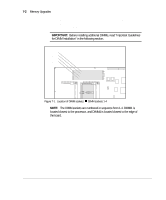
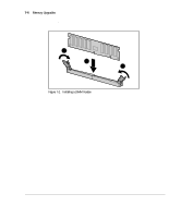
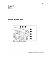
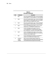
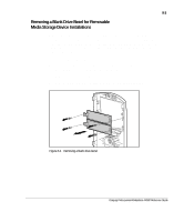
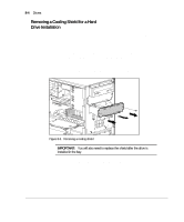
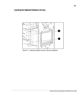
8-2 Drives As shown in Figure 8-1, drive bays 1 through 3 are located in the removable hard drive cage, which is located behind the side access panel of the workstation. Drive bays 4 through 7 are located on the front of the workstation. They support various drive configurations. Table 8-1 Drive Bay Components Ref. Component Description 1 Bay 1 Part of the removable hard drive cage. A 3.5-inch, third-height bay that supports a 1.0-inch hard drive or a 1.6-inch hard drive. 2 Bay 2 Part of the removable hard drive cage. A 3.5-inch, third-height bay that supports a 1.0-inch hard drive. Bay 2 is not available when a 1.6-inch drive is installed in bay 1 or bay 3. 3 Bay 3 Part of the removable hard drive cage. A 3.5-inch, third-height bay that supports a 1.0-inch hard drive or 1.6-inch hard drive. 4 Bay 4 5.25-inch, half-height bay that supports 1.0-inch or 1.6-inch storage devices. A CD-ROM drive is shipped in bay 4. 5 Bay 5 5.25-inch, half-height bay that supports 1.0-inch or a 1.6-inch storage devices. An optional hard drive, diskette drive, CD-ROM drive, or tape drive can be installed in bay 5. 6 Bay 6 5.25-inch, half-height bay that supports 1.0-inch or 1.6-inch devices. An optional hard drive, diskette drive, CD-ROM drive, or tape drive can be installed in bay 6. 7 Bay 7 3.5-inch, third-height bay that supports a 1.0-inch device. A standard 3.5-inch diskette drive is shipped in bay 7. 8 Air plenum (cooling chamber) Side of air plenum provides temporary storage for the hardware screws used to install optional mass storage devices in the removable hard drive cage and in the front bays.
-
 1
1 -
2
-
3
-
4
-
5
-
6
-
7
-
8
-
9
-
10
-
11
-
12
-
13
-
14
-
15
-
16
-
17
-
18
-
19
-
20
-
21
-
22
-
23
-
24
-
25
-
26
-
27
-
28
-
29
-
30
-
31
-
32
-
33
-
34
-
35
-
36
-
37
-
38
-
39
-
40
-
41
-
42
-
43
-
44
-
45
-
46
-
47
-
48
-
49
-
50
-
51
-
52
-
53
-
54
-
55
-
56
-
57
-
58
-
59
-
60
-
61
-
62
-
63
-
64
-
65
-
66
-
 67
67 -
 68
68 -
 69
69 -
 70
70 -
 71
71 -
 72
72 -
 73
73 -
 74
74 -
 75
75 -
 76
76 -
 77
77 -
78
-
79
-
80
-
81
-
82
-
83
-
84
-
85
-
86
-
87
-
88
-
89
-
90
-
91
-
92
-
93
-
94
-
95
-
96
-
97
-
98
-
99
-
100
-
101
-
102
-
103
-
104
-
105
-
106
-
107
-
108
-
109
-
110
-
111
-
112
-
113
-
114
-
115
-
116
-
117
-
118
-
119
-
120
-
121
-
122
-
123
-
124
-
125
-
126
-
127
-
128
-
129
-
130
-
131
-
132
-
133
-
134
-
135
-
136
-
137
-
138
-
139
-
140
 |
 |