HP Xw9400 HP xw9400 Workstation - Service and Technical Reference Guide
HP Xw9400 - Workstation - 16 GB RAM Manual
 |
View all HP Xw9400 manuals
Add to My Manuals
Save this manual to your list of manuals |
HP Xw9400 manual content summary:
- HP Xw9400 | HP xw9400 Workstation - Service and Technical Reference Guide - Page 1
HP xw9400 Workstation Service and Technical Reference Guide - HP Xw9400 | HP xw9400 Workstation - Service and Technical Reference Guide - Page 2
. No part of this document may be photocopied, reproduced, or translated to another language without the prior written consent of Hewlett-Packard Company. Trademark Credits The HP Invent logo is a trademark of HewlettPackard Company in the U.S. and other countries. Microsoft and Windows are - HP Xw9400 | HP xw9400 Workstation - Service and Technical Reference Guide - Page 3
slot power specification 10 Chipkill support ...11 ENERGY STAR Qualification ...11 Multi-core processors ...12 2 Setting up the operating system Setting up the Microsoft operating system 14 Installing or upgrading device drivers 14 Transferring files and settings to your Windows workstation 14 - HP Xw9400 | HP xw9400 Workstation - Service and Technical Reference Guide - Page 4
23 4 System management Computer Setup (F10) Utility ...25 BIOS ROM ...26 Using Computer Setup (F10) Utility 27 Computer Setup (F10) Utility menu 28 Desktop management ...36 Initial configuration and deployment 36 Remote system installation 37 Managing and updating software 37 HP Client Manager - HP Xw9400 | HP xw9400 Workstation - Service and Technical Reference Guide - Page 5
power-on or setup password 46 Deleting a power-on or setup password 47 National keyboard delimiter characters 47 Clearing passwords 47 Hood sensor (Smart Cover Sensor 48 Setting the hood sensor protection level 48 Cable lock provision (optional 48 Security lock (optional 48 Universal chassis - HP Xw9400 | HP xw9400 Workstation - Service and Technical Reference Guide - Page 6
bay 98 Liquid cooling unit ...99 Removing the liquid cooling unit 99 Installing a liquid cooling unit 103 Replacing the liquid cooling unit VRD fan 110 Removing the VRD fan 110 Installing the VRD fan 111 Processor heatsink ...113 Removing the CPU heatsink 113 Replacing the CPU heatsink 115 - HP Xw9400 | HP xw9400 Workstation - Service and Technical Reference Guide - Page 7
the processor 119 System board ...120 Removing the system board 120 Replacing the System Board 120 Product recycling ...121 6 System diagnostics and troubleshooting HP troubleshooting resources and tools 122 HP Help and Support Center 122 E-support ...122 Troubleshooting a problem 123 - HP Xw9400 | HP xw9400 Workstation - Service and Technical Reference Guide - Page 8
D- System board designators Appendix E Appendix E- Power cord set requirements Appendix F Appendix F- Routine care General cleaning safety precautions 187 Maximizing the airflow ...187 Cleaning the workstation case ...187 Cleaning the keyboard ...188 Cleaning the monitor ...188 Cleaning the mouse - HP Xw9400 | HP xw9400 Workstation - Service and Technical Reference Guide - Page 9
device list ...209 Appendix J Appendix J- Configuring SATA and PATA optical disk drives Drive detection and assignment sequence 211 Workstation SATA port configuration rules 211 HP w9400 Workstation BIOS configuration 211 HP xw8400/xw6400/xw4400 Workstation SATA configuration mode settings 211 - HP Xw9400 | HP xw9400 Workstation - Service and Technical Reference Guide - Page 10
x ENWW - HP Xw9400 | HP xw9400 Workstation - Service and Technical Reference Guide - Page 11
accessories and components, see http://partsurfer.hp.com. Figure 1-1 Exploded view Table 1-1 Exploded view Item Description 1 PCI card support 2 Power supply 3 CPU heatsinks 4 Processors ENWW Item Description 10 Memory modules 11 Card guide/Front fan 12 Graphics card 13 Optical - HP Xw9400 | HP xw9400 Workstation - Service and Technical Reference Guide - Page 12
1-1 Exploded view (continued) Item Description 5 System fan 6 Access panel 7 System board 8 Chassis 9 Front bezel * A CD-ROM is an example of an optical drive. Item Description 14 PCIe card 15 Diskette drive 16 PCI card 17 Hard drive 18 Memory fan 2 Chapter 1 Product overview ENWW - HP Xw9400 | HP xw9400 Workstation - Service and Technical Reference Guide - Page 13
Front panel components The following image shows a typical HP xw9400 Workstation. Drive configurations can vary. Figure 1-2 Front panel components Table 1-2 Front 6 Headphone connector 7 USB 2.0 ports 8 Hard drive activity light 9 Power button 10 Power on light ENWW Product features 3 - HP Xw9400 | HP xw9400 Workstation - Service and Technical Reference Guide - Page 14
devices. ** SPDIF OUT is a single RCA jack to support SPDIF digital audio output via coax cable. Serial number and COA label location Each workstation has two unique serial number labels. Systems preinstalled with Microsoft® Windows® XP also have a certificate of authentication (COA) label - HP Xw9400 | HP xw9400 Workstation - Service and Technical Reference Guide - Page 15
when contacting customer service for assistance. Figure 1-4 Serial number and COA label location Product specifications The following table lists the physical dimensions. Table 1-4 Physical characteristics Weight (depending on 18-27.7 kg (39.6-61.1 lb.) configuration) Tower dimensions 455 - HP Xw9400 | HP xw9400 Workstation - Service and Technical Reference Guide - Page 16
that supplies power to memory PCI, PCIe, and system fans Storage (hard drive, optical drive, diskette drive) PCI Express auxiliary connector Second PCI Express auxiliary connector Not used PCI and serial ports Sleep circuitry Table 1-6 Maximum current per rail Voltage rail 1050W maximum continuous - HP Xw9400 | HP xw9400 Workstation - Service and Technical Reference Guide - Page 17
CAUTION: Do not exceed 150 watts of 3.3V and 5V power combination. Do not exceed 84.0 amps (1008W) of 12V (CPU0/CPU1/M/B/D/G1/G2/R) power combination. Do not exceed 1050 watts of total continuous output power. ENWW Product specifications 7 - HP Xw9400 | HP xw9400 Workstation - Service and Technical Reference Guide - Page 18
supply configurations. To review available specifications, see http://www.hp.com/go/quickspecs. To reach zero power consumption, unplug the workstation from the power outlet or use a power strip with an on/off switch. For additional information about power-saving features, see your operating system - HP Xw9400 | HP xw9400 Workstation - Service and Technical Reference Guide - Page 19
and airflow The workstation includes one rear system fan, one memory fan, one processor (CPU) heatsink fan for each processor, and one power supply fan, plus a front system fan. Resetting the power supply If an overload triggers the power supply overload protection, all power is immediately shut - HP Xw9400 | HP xw9400 Workstation - Service and Technical Reference Guide - Page 20
to these slot power specifications, the overall power consumption of the system (including I/O cards, processor, and memory) must not exceed the maximum ratings of the system power supply. See Power supply specifications on page 8 for details. ** Includes 75 W maximum from the system board connector - HP Xw9400 | HP xw9400 Workstation - Service and Technical Reference Guide - Page 21
. For hardware specifications of other system components, such as graphics cards or optical drives, see the website of the specific manufacturer. Chipkill support Chipkill is a form of advanced Error Checking and Correcting (ECC) computer memory technology. The HP xw9400 Workstation supports 128-bit - HP Xw9400 | HP xw9400 Workstation - Service and Technical Reference Guide - Page 22
system, you must also reset the ENERGY STAR settings (if applicable) after the restore. To verify the factory default power settings for your workstation, select Start>Control Panel, and then double-click Power Options. Multi-core processors This HP Workstation supports selected AMD Opteron - HP Xw9400 | HP xw9400 Workstation - Service and Technical Reference Guide - Page 23
up the Microsoft operating system on page 14 Setting up Red Hat Enterprise Linux on page 15 Setting up Novell SLED on page 16 Updating the workstation on page 16 This chapter also includes information on how to determine that you have the latest BIOS, drivers, and software updates installed on the - HP Xw9400 | HP xw9400 Workstation - Service and Technical Reference Guide - Page 24
must have the most recent updates, patches, and software fixes. For additional driver and software update information, refer to Upgrading device drivers on page 18. Transferring files and settings to your Windows workstation The Microsoft Windows operating system offers data migration tools that - HP Xw9400 | HP xw9400 Workstation - Service and Technical Reference Guide - Page 25
at http://www.hp.com/support/workstation_swdrivers. Installing with the HP driver CD To install the HP driver CD, see "Installing with the HP Installer Kit for Linux" in the HP Workstations for Linux manual at http://www.hp.com/support/workstation_manuals. ENWW Setting up Red Hat Enterprise - HP Xw9400 | HP xw9400 Workstation - Service and Technical Reference Guide - Page 26
your system. See Upgrading device drivers on page 18 for instructions. ● Become familiar with your available HP resources. ● Consider a subscription to Driver Alerts at http://www.hp.com/go/subscriberschoice. Upgrading the BIOS For optimum performance, determine the BIOS revision on the workstation - HP Xw9400 | HP xw9400 Workstation - Service and Technical Reference Guide - Page 27
screen. 2. Press F10 to enter the F10 Setup utility. The F10 Setup utility displays the workstation BIOS version under File > System Information. 3. Note the workstation BIOS version so that you can compare it with the BIOS versions that appear on the HP website. ENWW Updating the workstation 17 - HP Xw9400 | HP xw9400 Workstation - Service and Technical Reference Guide - Page 28
than the one on your system, download the appropriate version for the workstation. Follow the instructions in the release notes to complete the installation. Upgrading device drivers If you install a peripheral device (such as a printer, display adapter, or network adapter), confirm you have the - HP Xw9400 | HP xw9400 Workstation - Service and Technical Reference Guide - Page 29
to restore the Windows or Linux operating system. It includes these topics: Topics Restore methods on page 19 Ordering backup software on page 20 Restoring Windows Vista on page 20 Restoring Windows XP Professional on page 21 Restoring Novell SLED on page 23 Installing with the HP driver CD on page - HP Xw9400 | HP xw9400 Workstation - Service and Technical Reference Guide - Page 30
, the media is included with your workstation components. If you did not order restore media, call HP Support and request a RestorePlus! media kit. For worldwide technical support phone numbers, visit http://www.hp.com/support. Restoring the operating system NOTE: Windows Vista provides a backup and - HP Xw9400 | HP xw9400 Workstation - Service and Technical Reference Guide - Page 31
prompts to create RestorePlus!, operating system, and HPBR media. If you are unable to create CD/DVDs on your workstation, call HP Support and request a RestorePlus! media kit. For worldwide technical support phone numbers, visit http://www.hp.com/support. ENWW Restoring Windows XP Professional 21 - HP Xw9400 | HP xw9400 Workstation - Service and Technical Reference Guide - Page 32
Creating HP Backup and Recovery (HPBR) media NOTE: HPBR functionality is used with Windows XP only. For details, refer to the SoftThinks guide on the Documentation and Diagnostics CD included with the workstation. The Initial Recovery Point can be burned to optical media and used to recover a system - HP Xw9400 | HP xw9400 Workstation - Service and Technical Reference Guide - Page 33
. Using RestorePlus! To restore with RestorePlus!: 1. Boot the workstation from the RestorePlus! DVD. You must start from the RestorePlus! DVD for device drivers and settings to be installed. 2. Follow the prompts to restore the operating system. Some application software might not be restored using - HP Xw9400 | HP xw9400 Workstation - Service and Technical Reference Guide - Page 34
NOTE: Make copies of the ISO recovery images on CD as backup files in case your workstation experiences a hard drive failure. 24 Chapter 3 Restoring the operating system ENWW - HP Xw9400 | HP xw9400 Workstation - Service and Technical Reference Guide - Page 35
features and password prompting during system reset and during power-on. ● Establish and manage energy-saving time-outs (not supported for Linux platforms). ● Set the system date and time. ● Set, view, and change the system configuration, including settings for processor, graphics, memory, audio - HP Xw9400 | HP xw9400 Workstation - Service and Technical Reference Guide - Page 36
POST, PCI device initialization, Plug 'n' Play support, power management activities, and the Computer Setup Utility. BIOS supports the following systems and specifications: ● Dual AMD Opteron 2xxx series processors ● Up to DDR2-667 memory ● HyperTransport setup and initialization ● Chipset (includes - HP Xw9400 | HP xw9400 Workstation - Service and Technical Reference Guide - Page 37
File>Default Setup>Restore Factory Settings as Default. Press F10 to accept the changes. Click File>Apply Defaults and Exit. This option restores the original factory system defaults. CAUTION: Do not turn the workstation power off while the ROM is saving your Computer Setup Utility changes because - HP Xw9400 | HP xw9400 Workstation - Service and Technical Reference Guide - Page 38
4-1 Computer Setup Utility menu descriptions Heading Option Description File System Lists product name, SKU number, processor type/speed/stepping, cache size Information (L1/L2), memory type and size, integrated Media Access Control (MAC) IDs for Network Interface, system BIOS type, chassis - HP Xw9400 | HP xw9400 Workstation - Service and Technical Reference Guide - Page 39
Description Hard Disk Identifies the hard disk drives on the system by model, firmware, serial number, connector color, emulation type, multisector transfers, and translation mode. By default, SATA drives are not listed here. Default values can be set here for IDE and SATA drives, but not for SAS - HP Xw9400 | HP xw9400 Workstation - Service and Technical Reference Guide - Page 40
to certain plug-and-play settings under Windows. Power-On Password Enables you to set and enable the power-on password. NOTE: If a power on-password is set, or the workstation cover removal sensor is activated, entries for these items will appear in this list. 30 Chapter 4 System management ENWW - HP Xw9400 | HP xw9400 Workstation - Service and Technical Reference Guide - Page 41
Unique Identifier) Can only be updated if the current chassis serial number is invalid. (These ID numbers are normally set in the factory and are used to uniquely identify the system.) Keyboard Enables you to set the keyboard locale for System ID entry. ENWW Computer Setup (F10) Utility 31 - HP Xw9400 | HP xw9400 Workstation - Service and Technical Reference Guide - Page 42
from running in pages that were set up as data pages, and prevents attacks such as buffer overflows. Operating system support is required for this feature. AMD Virtualization Technology Enables AMD Virtualization Technology to increase workstation performance. OS Management of Embedded Security - HP Xw9400 | HP xw9400 Workstation - Service and Technical Reference Guide - Page 43
special thermal/cooling needs may need to increase the minimum spinning speed of the fans in the system. They can do so by using this menu and selecting a higher minimal fan speed. BIOS Enables you to disable or specify a day and time for BIOS power-on. Power-On OS Power ACPI S3 Support (Enable - HP Xw9400 | HP xw9400 Workstation - Service and Technical Reference Guide - Page 44
device insertion. Execute Memory Test Chipset/ Memory System reboots and executes the memory test. ● Coherent HT: 1000 MHz, 2200 MHz default (Available on selected workstations). ● ECC Support (Enable/Disable) Enables/disables memory Error Correcting Code (ECC). Memory Scrubbing (Enable/Disable - HP Xw9400 | HP xw9400 Workstation - Service and Technical Reference Guide - Page 45
Allow manual configuration of system IRQs. For more details on using this feature and on maximizing interrupt performance, refer to the Optimizing APIC Interrupt Assignments on the xw9400 white paper available at http://tclperf.fc.hp.com/performance_briefs/index.htm. Onboard Devices Disable or set - HP Xw9400 | HP xw9400 Workstation - Service and Technical Reference Guide - Page 46
43 ● Fault notification and recovery on page 49 NOTE: Support for specific features described in this guide might vary by model or software version. Initial configuration and deployment The workstation comes with a preinstalled system software image. After a brief software unbundling process, the - HP Xw9400 | HP xw9400 Workstation - Service and Technical Reference Guide - Page 47
, application software, or drivers To initiate Remote System Installation, press F12 when F12=Network Service Boot appears in the lower-right corner of the HP logo screen. Follow the onscreen instructions to continue the process. The default boot order is a BIOS configuration setting that can be - HP Xw9400 | HP xw9400 Workstation - Service and Technical Reference Guide - Page 48
resolution ◦ Managing help desk tickets ◦ Remote troubleshooting ◦ Remote problem resolution ◦ Client disaster recovery ● Software and operations management ◦ Ongoing desktop management ◦ HP system software deployment ◦ Application self-healing See http://www.hp.com/go/ssm for more information about - HP Xw9400 | HP xw9400 Workstation - Service and Technical Reference Guide - Page 49
the latest ROMPaq images from HP driver and support page, http://www.hp.com/ support/files. NOTE: For maximum ROM protection, be sure to establish a setup password. The setup password prevents unauthorized ROM upgrades. System Software Manager enables you to set the setup password on one or more PCs - HP Xw9400 | HP xw9400 Workstation - Service and Technical Reference Guide - Page 50
: Workstation models that support recovery from a ROMPaq CD provide ISO ROMPaq images in the downloadable ROM SoftPaq. When the Boot Block detects an invalid system ROM, the System Power LED blinks red eight times, once every second, followed by a two-second pause. Also, you will hear eight beeps - HP Xw9400 | HP xw9400 Workstation - Service and Technical Reference Guide - Page 51
. To collect and replicate BIOS settings on multiple computers, use System Software Manager or HP Client Manager Software. For more information, see http://www.hp.com/go/easydeploy. Copying to a single workstation CAUTION: A setup configuration is model-specific. File system corruption can result if - HP Xw9400 | HP xw9400 Workstation - Service and Technical Reference Guide - Page 52
the instructions on the screen to create the configuration diskette or USB. 7. Download a BIOS utility for replicating setup (repset.exe), and copy it onto the configuration diskette or USB. To obtain this utility, go to http://www.hp.com/support/files and enter the model number of the workstation - HP Xw9400 | HP xw9400 Workstation - Service and Technical Reference Guide - Page 53
can download the software from http://www.hp.com/support. The Web site contains the latest device drivers, utilities, and flashable ROM images needed to run the latest Microsoft Windows operating system on the HP workstation. Building blocks and partners HP management solutions integrate with other - HP Xw9400 | HP xw9400 Workstation - Service and Technical Reference Guide - Page 54
password specifically prevents unauthorized access to the Computer Setup Utility and can also be used as an override to the power-on password. That is, when prompted for the power-on password, entering the setup password instead will allow access to the workstation. 44 Chapter 4 System management - HP Xw9400 | HP xw9400 Workstation - Service and Technical Reference Guide - Page 55
know the power-on password. NOTE: System Software Manager and HP Client Manager Software allow remote management of setup passwords and other BIOS settings in a networked environment. For more information, see http://www.hp.com/go/easydeploy. Establishing a setup password in the Computer Setup (F10 - HP Xw9400 | HP xw9400 Workstation - Service and Technical Reference Guide - Page 56
to enter it each time you run the Computer Setup Utility. To enter a setup password: 1. Power on or restart the workstation. 2. As soon as the screen illuminates, press and hold the F10 key until you enter the Computer Setup Utility. Press Enter to bypass the title screen, if necessary. NOTE: If you - HP Xw9400 | HP xw9400 Workstation - Service and Technical Reference Guide - Page 57
password To delete a power-on or setup password: 1. Power on or restart the workstation. 2. To delete the power-on password, go to step 3. To delete the setup password, as soon as the screen illuminates, press and hold the F10 key until you enter the Computer Setup Utility. Press Enter to bypass - HP Xw9400 | HP xw9400 Workstation - Service and Technical Reference Guide - Page 58
has been removed. You must enter the setup password to continue. * These settings can be changed using the Computer Setup Utility. Setting the hood sensor protection level To set the hood sensor protection level: 1. Power on or restart the workstation. 2. As soon as the screen illuminates, press - HP Xw9400 | HP xw9400 Workstation - Service and Technical Reference Guide - Page 59
the loss of critical data and minimize unplanned downtime. If the workstation is connected to a network managed by HP Client Manager software, the computer sends a fault notice to the network management application. With HP Client Manager software, you can also remotely schedule diagnostics to - HP Xw9400 | HP xw9400 Workstation - Service and Technical Reference Guide - Page 60
System board components on page 56 ● System board the surface to cool before touching. WARNING power cord from the electrical outlet. WARNING! To reduce the risk of serious injury, read the Safety & Comfort Guide. It describes proper workstation setup, posture, health, and work habits for computer - HP Xw9400 | HP xw9400 Workstation - Service and Technical Reference Guide - Page 61
of the workstation. Also, review the Safety and Regulatory Guide that came with your workstation for more information. WARNING! Some parts inside the computer will be hot. Power off and unplug the system, and wait three to five minutes for them to cool before opening the system access panels - HP Xw9400 | HP xw9400 Workstation - Service and Technical Reference Guide - Page 62
. ● When handling or touching a sensitive component or assembly, ground yourself by touching the chassis. ● Avoid contact with pins, leads, or circuitry. ● Place reusable electrostatic-sensitive parts from assemblies in protective packaging or conductive foam. 52 Chapter 5 Removal and replacement - HP Xw9400 | HP xw9400 Workstation - Service and Technical Reference Guide - Page 63
workstations and are compatible with most types of shoes or boots. On conductive floors or dissipative floor mats, use them on both feet with a maximum parts, and assemblies by the case or PCB laminate. Handle them only at static-free work areas. ● Turn off power . ● Use field service tools, such as - HP Xw9400 | HP xw9400 Workstation - Service and Technical Reference Guide - Page 64
cases, avoid bending or twisting the cables, and be sure that the cables are routed in such a way that they cannot be caught or snagged by parts being removed or replaced. CAUTION: When servicing this workstation drive, power off the workstation. Do not remove a hard drive while the workstation is on - HP Xw9400 | HP xw9400 Workstation - Service and Technical Reference Guide - Page 65
drive to liquids, temperature extremes, or products that have magnetic fields such as monitors or speakers. Lithium coin cell battery The battery that comes with the workstation provides power to the real-time clock and has a minimum lifetime of about three years. For instructions on battery removal - HP Xw9400 | HP xw9400 Workstation - Service and Technical Reference Guide - Page 66
image shows the system board connectors and sockets on the HP xw9400 Workstation. Figure 5-1 System board identification Table 5-3 System board components Ite Description Item Description Item Description m 1 Main power 13 Memory fan 25 Front control panel 2 Memory module 14 PCI Express - HP Xw9400 | HP xw9400 Workstation - Service and Technical Reference Guide - Page 67
recovery jumper 47 Memory power 12 Audio 24 Front IEEE 1394 36 PCI fan * The PCI Express x16 is a PCI Express x16 connector that has x8 bandwidth. ** The Primary IDE connector is generally used for optical drives. System board architecture The following image shows the HP xw9400 Workstation - HP Xw9400 | HP xw9400 Workstation - Service and Technical Reference Guide - Page 68
components on your workstation. Before servicing or upgrading your workstation: 1. Review the safety precautions and the Service considerations on page 51, as well as the Safety and Regulatory Information. 2. Locate and clear a suitable work area. 3. Shut down the system and remove power from the - HP Xw9400 | HP xw9400 Workstation - Service and Technical Reference Guide - Page 69
drive (Diskette drive (optional) on page 93) Bezel blanks (Bezel blanks on page 64) Power supply (Power supply on page 69) System fan (System fan on page 70) Memory fan (Memory fan on page 71) Memory (Memory on page 72) Front fan removal (optional) (Front fan removal on page 84) Battery (Battery - HP Xw9400 | HP xw9400 Workstation - Service and Technical Reference Guide - Page 70
(PCI retention clamp on page 80) PCI or PCI Express card (Removing PCI or PCI Express cards on page 82) CPU heatsink (Removing the CPU heatsink on page 113) Processor (Removing the processor on page 117) System board (System board on page 120) 60 Chapter 5 Removal and replacement procedures ENWW - HP Xw9400 | HP xw9400 Workstation - Service and Technical Reference Guide - Page 71
the padlock loop as shown in the following image. Figure 5-3 Removing the security lock Cable lock (optional) If a cable lock is installed, remove it before servicing the unit. To remove the cable lock, unlock it and pull it out of the cable lock slot as shown in the following image. Figure - HP Xw9400 | HP xw9400 Workstation - Service and Technical Reference Guide - Page 72
Universal chassis clamp lock (optional) If a universal chassis clamp lock is installed, remove it before servicing the unit. To remove the lock: 1. Unlock the device and remove the locking mechanism. 2. Remove the screw attaching the lock to the chassis. 62 Chapter 5 Removal and replacement - HP Xw9400 | HP xw9400 Workstation - Service and Technical Reference Guide - Page 73
workstation access panel, be sure that the workstation is powered off and that the power cord is disconnected from the electrical outlet. 1. Disconnect power from the system bottom edge of the chassis. Rotate the access panel toward the chassis and press firmly until the latch engages. ENWW - HP Xw9400 | HP xw9400 Workstation - Service and Technical Reference Guide - Page 74
located on the front bezel. 2. Rotate the front bezel away (2) from the chassis, and remove the bezel. Figure 5-6 Opening the front bezel Bezel blanks To remove the bezel blanks: 1. Disconnect power from the system, (Pre-disassembly procedures on page 55), remove the access panel, and remove the - HP Xw9400 | HP xw9400 Workstation - Service and Technical Reference Guide - Page 75
cover sensor) To remove the hood sensor: 1. Disconnect power from the system (Pre-disassembly procedures on page 55) and remove the access panel (Access panel on page 63). Remove the front bezel. Lay the workstation on its side with the system board facing up. 2. Remove the two hood sensor bracket - HP Xw9400 | HP xw9400 Workstation - Service and Technical Reference Guide - Page 76
remove the front panel I/O device assembly: 1. Disconnect power from the system (Pre-disassembly procedures on page 55). Remove the snap that secures the cables inside the chassis and, disconnect the front panel I/O device assembly cables from the system board. 3. Remove the screws that hold the - HP Xw9400 | HP xw9400 Workstation - Service and Technical Reference Guide - Page 77
page 66). 3. Disconnect the power button assembly cable from the system board. 4. Disconnect the speaker wire and the hood sensor from the inline connectors on the power button assembly cable. 5. Remove the screw (1) that secures the power button assembly to the chassis. 6. Dislodge the metal clip - HP Xw9400 | HP xw9400 Workstation - Service and Technical Reference Guide - Page 78
2. Slide the speaker away from the three flanges and remove it from the chassis. Figure 5-11 Removing the speaker 68 Chapter 5 Removal and replacement procedures ENWW - HP Xw9400 | HP xw9400 Workstation - Service and Technical Reference Guide - Page 79
procedures on page 55), and remove the access panel (Access panel on page 63). Place the workstation on its side with the system board facing up. 2. Disconnect the three power supply cable connectors from the system board. NOTE: Cable ties and cable clips may be present. 3. Disconnect the - HP Xw9400 | HP xw9400 Workstation - Service and Technical Reference Guide - Page 80
Place the workstation on its side with the system board facing up. 2. Disconnect the fan power plug from the system board (1). 3. Press down on the ribbed portion of the system fan housing (2), rotate the fan housing down, and lift the unit out of the chassis. Figure 5-13 Removing the system fan To - HP Xw9400 | HP xw9400 Workstation - Service and Technical Reference Guide - Page 81
procedures on page 55), and remove the access panel (Access panel on page 63). Place the workstation on its side with the system board facing up. 2. Disconnect the memory fan power plug from the system board (1). NOTE: If the fan is simply being moved to access the DIMMs, it does not need - HP Xw9400 | HP xw9400 Workstation - Service and Technical Reference Guide - Page 82
1-GB , 2-GB, 4-GB, and 8-GB DIMMs ● 64-GB maximum configuration with 8-GB DIMMs ● Standard ECC PC2-5300 DIMMs ● No support for mirroring ● No spare DIMM support Memory module requirements ● Use only PC2-5300 ECC DIMMs. Certified and warranted HP memory is recommended. ● Match DIMM pairs by size and - HP Xw9400 | HP xw9400 Workstation - Service and Technical Reference Guide - Page 83
side with the system board facing up. CAUTION: To ensure that memory modules are not damaged during removal or installation, power off the workstation and unplug the power cord from the AC power outlet. Wait until the LED on the back of the power supply turns off before removing memory. If you do - HP Xw9400 | HP xw9400 Workstation - Service and Technical Reference Guide - Page 84
4. Lift the DIMM straight up, and remove it from the unit (2). Figure 5-16 Removing DIMM NOTE: DIMMs and DIMM sockets are keyed for proper installation. Be sure these guides align when installing a DIMM. 74 Chapter 5 Removal and replacement procedures ENWW - HP Xw9400 | HP xw9400 Workstation - Service and Technical Reference Guide - Page 85
compatible, they are not supported by HP. 1. Disconnect power from the system (Pre-disassembly procedures on page 55) and remove the access panel (Access panel on page 63). Lay the workstation on its side with the system board facing up. 2. Depress the green tabs on the memory fan housing (1) and - HP Xw9400 | HP xw9400 Workstation - Service and Technical Reference Guide - Page 86
fan housing when lowering the memory fan. The BIOS generates warnings/errors on invalid memory configurations. ● If BIOS cannot obtain a valid memory configuration, it will halt the system with a diagnostics 2006 code for memory error (five beeps and blinks). ● If memory node interleave is enabled - HP Xw9400 | HP xw9400 Workstation - Service and Technical Reference Guide - Page 87
PCI slots Figure 5-19 Identifying PCI slots Table 5-4 PCI slots Slot Type Ref 1 PCI Express x16 (x8) J31 2 PCI Express x16 graphics J41 3 PCI 32 bit, 33 MHz J20 4 PCI Express x16 (x8) J33 5 PCI Express x16 graphics J32 6 PCI-X 100 J25 7 PCI-X 100/133 J26 ENWW Removing and - HP Xw9400 | HP xw9400 Workstation - Service and Technical Reference Guide - Page 88
of the chassis. Figure 5-20 Removing the short or tall card PCI retainer Installing the PCI retainer 1. Disconnect power from the system (Pre-disassembly procedures on page 55), and remove the access panel (Access panel on page 63). Place the workstation on its side with the system board facing up - HP Xw9400 | HP xw9400 Workstation - Service and Technical Reference Guide - Page 89
both short and tall PCI cards, attach the hooks of the PCI retainer (1) under the slots on the rear of the chassis, and then rotate the retainer down until the retainer arm (2) supports the card. Figure 5-21 Installing the short or tall card PCI retainer ENWW Removing and replacing components 79 - HP Xw9400 | HP xw9400 Workstation - Service and Technical Reference Guide - Page 90
PCI retention clamp 1. Disconnect power from the system (Pre-disassembly procedures on page 55), and remove the access panel (Access panel on page 63). Place the workstation on its side with the system board facing up. 2. Open the PCI retention clamp by pressing down on the two green clips at the - HP Xw9400 | HP xw9400 Workstation - Service and Technical Reference Guide - Page 91
CPU and the memory subsystem.) The transmission protocol is somewhat similar to that used for a LAN connection and contains error correction and detection, packet addressing, and other network features. PCI Express improves system attributes. PCI Express enables a low-power matrix for xw9400 Slot - HP Xw9400 | HP xw9400 Workstation - Service and Technical Reference Guide - Page 92
Removing PCI or PCI Express cards 1. Disconnect power from the system (Pre-disassembly procedures on page 55), and remove the access panel (Access panel on page 63). Place the workstation on its side with the system board facing up. Remove the PCI retainer (PCI retainer on page 78) if present. 2. - HP Xw9400 | HP xw9400 Workstation - Service and Technical Reference Guide - Page 93
PCI or PCI Express installation 1. Disconnect power from the system (Pre-disassembly procedures on page 55), and remove the access panel (Access panel on page 63). Place the workstation on its side with the system board facing up, and remove the PCI retainer (PCI retention clamp on page 80). 2. Open - HP Xw9400 | HP xw9400 Workstation - Service and Technical Reference Guide - Page 94
Front fan removal To remove the front fan: 1. Disconnect power from the system (Pre-disassembly procedures on page 55), and remove the access panel (Access panel on page 63). Place the workstation on its side with the system board facing up. 2. Disconnect optical and floppy drive cables from the - HP Xw9400 | HP xw9400 Workstation - Service and Technical Reference Guide - Page 95
5-28 Installing the fan in card guide 4. Lower the card guide with installed fan into the chassis. Place the card guide tabs into the chassis slots and snap the card guide into place. 5. Plug the front fan cable into its connector on the system board. ENWW Removing and replacing components 85 - HP Xw9400 | HP xw9400 Workstation - Service and Technical Reference Guide - Page 96
an HP xw9400 Workstation when a 4 GB or greater DIMM is used in the workstation. The additional jumper cable provides for quieter fan operation. 1. Disconnect the front system fan cable from the system board. Figure 5-29 Disconnect front system fan cable from system board 2. Connect the system fan - HP Xw9400 | HP xw9400 Workstation - Service and Technical Reference Guide - Page 97
5-31 Place excess cable in chassis 4. Connect the system fan jumper cable to the front fan cable connector on the system board. Use the system board connector to which the original front fan cable connected. Figure 5-32 Connect system fan jumper cable to system board ENWW Removing and replacing - HP Xw9400 | HP xw9400 Workstation - Service and Technical Reference Guide - Page 98
CMOS settings, use Computer Setup and run the Save to Diskette option from the File menu. To remove the battery: 1. Disconnect power from the system (Pre-disassembly procedures on page 55), and remove the access panel (Access panel on page 63). Place the workstation on its side with the system board - HP Xw9400 | HP xw9400 Workstation - Service and Technical Reference Guide - Page 99
so that they cannot interfere with the CPU heatsink fans. Figure 5-34 Identifying correct power connections Table 5-6 Power connector descriptions Connector Description P1 24-pin main power connector P2 4-pin memory power connector P3 8-pin processor power connector P4-P8 SATA and IDE - HP Xw9400 | HP xw9400 Workstation - Service and Technical Reference Guide - Page 100
Optical drive Your workstation might have a SATA or an IDE optical drive. To remove the optical drive: 1. Disconnect power from the system (Pre-disassembly procedures on page 55) and remove the access panel (Access panel on page 63). 2. Disconnect the audio (1), data (2), and power (3) cables from - HP Xw9400 | HP xw9400 Workstation - Service and Technical Reference Guide - Page 101
to the drive and workstation. NOTE: The audio cable is only required for Linux-based systems. 3. If you are installing more than one optical drive, route the cable as in the following image. Figure 5-37 Connecting IDE (left) or SATA (right) optical drive cable to system board ENWW Removing and - HP Xw9400 | HP xw9400 Workstation - Service and Technical Reference Guide - Page 102
with currently available HP Professional Displays are compliant. Older HP xw4600 and xw9400 Workstation configurations may not have fully compliant paths based on the installed graphics card and display monitor; HP recommends confirming separately that you have a fully compliant system if commercial - HP Xw9400 | HP xw9400 Workstation - Service and Technical Reference Guide - Page 103
drive (optional) To remove a diskette drive: 1. Disconnect power from the system (Pre-disassembly procedures on page 55). Remove the access panel (Access panel on page 63) and the front bezel (Front bezel on page 64). 2. Disconnect the data and power cables from the back of the diskette drive - HP Xw9400 | HP xw9400 Workstation - Service and Technical Reference Guide - Page 104
the drive into the chassis. 3. Route the diskette drive data cable between the system board and the hard drive cage. Your cable might look different than the one shown. Connect the data and power cables to the diskette drive. Ensure that the power cable is connected to the system board. Figure 5-41 - HP Xw9400 | HP xw9400 Workstation - Service and Technical Reference Guide - Page 105
Hard drive Replacing a hard drive For more information on SATA hard drives and the SATA RAID configuration, see Appendix B-SATA devices on page 172. Removing a hard drive 1. Disconnect power from the system (Pre-disassembly procedures on page 55), and remove the access panel (Access panel on page 63 - HP Xw9400 | HP xw9400 Workstation - Service and Technical Reference Guide - Page 106
Installing a hard drive 1. Select a drive bay in which to install the drive. If installing more than one hard drive, use the hard drive order shown in the following image. Figure 5-43 Identifying hard drive installation order 2. Squeeze the green tabs, and slide the rails out of the empty bay. 3. - HP Xw9400 | HP xw9400 Workstation - Service and Technical Reference Guide - Page 107
drive, attach a SAS/SATA adapter to the connector on the hard drive. Attach a data cable from a SAS connector on the system board to the hard drive, and attach a power cable to the drive. Figure 5-46 Installing the SAS/SATA adapter (left) and cable (right) ENWW Removing and replacing components 97 - HP Xw9400 | HP xw9400 Workstation - Service and Technical Reference Guide - Page 108
and tighten them to secure the hard drive to the chassis. 4. Attach a data cable from a SATA connector on the system board to the hard drive, and attach the fifth drive power cable to the drive. It is attached to a clip in front of the power supply. Figure 5-48 Attaching the data cable for the SATA - HP Xw9400 | HP xw9400 Workstation - Service and Technical Reference Guide - Page 109
describe removal of a liquid cooling unit. 1. Disconnect power from the system (Pre-disassembly procedures on page 55), and remove the access panel (Access panel on page 63). Place the workstation on its side with the system board facing up. 2. Loosen the two liquid cooling unit/radiator mounting - HP Xw9400 | HP xw9400 Workstation - Service and Technical Reference Guide - Page 110
position. Figure 5-50 Raise the radiator 4. Disconnect the memory fan (1), radiator fan (2), and voltage regulator fan (3) cables from the system board. Pull the memory fan cable clear of the liquid cooling unit. Figure 5-51 Disconnect memory, radiator, and voltage regulator fan cables 100 Chapter - HP Xw9400 | HP xw9400 Workstation - Service and Technical Reference Guide - Page 111
the two liquid cooling unit/CPU 1 mounting screws from the liquid cooling unit. Figure 5-52 Loosen liquid cooling unit/CPU 1 mounting screws 6. Lower the fan/radiator to its closed position. 7. For convenience, disconnect the PSU (1) cable from the system board. Disconnect the liquid cooling unit - HP Xw9400 | HP xw9400 Workstation - Service and Technical Reference Guide - Page 112
voltage regulator heatsink or the thermal compound on the processor. 10. If desired, loosen the liquid cooling unit chassis bracket screws and remove the bracket from the chassis. (This is necessary if the system board is to be removed.) Figure 5-55 Remove liquid cooling unit chassis bracket 102 - HP Xw9400 | HP xw9400 Workstation - Service and Technical Reference Guide - Page 113
installation of a liquid cooling unit. 1. Disconnect power from the system (Pre-disassembly procedures on page 55), and remove the access panel (Access panel on page 63). Place the workstation on its side with the system board facing up. 2. Install the liquid cooling unit rear chassis bracket if it - HP Xw9400 | HP xw9400 Workstation - Service and Technical Reference Guide - Page 114
disconnect the P3 power connector from the system board. 6. Place the liquid cooling unit fan/radiator is in its upright position. Align the liquid cooling unit rear guide pins to the notches in the rear cover guide while slowly lowering the liquid cooling unit into the chassis. WARNING! Be careful - HP Xw9400 | HP xw9400 Workstation - Service and Technical Reference Guide - Page 115
7. Lower the liquid cooling unit fan/radiator. 8. Install the workstation memory fan. Lower the memory fan assembly into the workstation chassis and snap it into place. Figure 5-60 Removing the memory fan 9. Guide the memory fan cable through the liquid cooling unit radiator tubing as shown in the - HP Xw9400 | HP xw9400 Workstation - Service and Technical Reference Guide - Page 116
Connect memory fan cable 12. Connect the cables for the radiator fan (1) and voltage regulator fan (2) to the system board. For convenience, you may remove any nearby PC card from its slot while you connect cables. CAUTION: Ensure that no cables interfere with the liquid cooling unit's system board - HP Xw9400 | HP xw9400 Workstation - Service and Technical Reference Guide - Page 117
lbs. Figure 5-64 Tighten liquid cooling unit/CPU 1 mounting screws 14. Lower the radiator to its closing position. 15. Alternately and evenly tighten the liquid cooling unit/CPU 0 mounting screws to a torque of 6 in./ lbs. Figure 5-65 Tighten liquid cooling unit/CPU 0 mounting screws ENWW Removing - HP Xw9400 | HP xw9400 Workstation - Service and Technical Reference Guide - Page 118
16. Tighten the radiator mounting screws. Figure 5-66 Position radiator and tighten mounting screws 17. Connect the liquid cooling unit pump cable to the system board. Figure 5-67 Connect pump cable to system board 108 Chapter 5 Removal and replacement procedures ENWW - HP Xw9400 | HP xw9400 Workstation - Service and Technical Reference Guide - Page 119
18. If appropriate, reconnect power cable P3 to the system board. Figure 5-68 Reconnect P3 to system board 19. If appropriate, reconnect power cables P15 and/or P16 to the graphics cards. ENWW Removing and replacing components 109 - HP Xw9400 | HP xw9400 Workstation - Service and Technical Reference Guide - Page 120
VRD fan This section explains how to replace the VRD fan in the liquid cooling unit. Removing the VRD fan To remove the VRD fan: 1. Remove the VRD cable from the cable channel. 2. Remove the VRD fan from its holder. - HP Xw9400 | HP xw9400 Workstation - Service and Technical Reference Guide - Page 121
Installing the VRD fan To install the VRD fan: 1. Position the VRD fan such that the indicator arrow on the fan points in the same direction as the indicator arrow in the fan holder. 2. Insert the fan in its holder. 3. Press down until the fan snaps into place. ENWW Removing and replacing - HP Xw9400 | HP xw9400 Workstation - Service and Technical Reference Guide - Page 122
4. Position the VRD cable in the cable channel. 112 Chapter 5 Removal and replacement procedures ENWW - HP Xw9400 | HP xw9400 Workstation - Service and Technical Reference Guide - Page 123
procedures listed are sufficient to assist you in removing the CPU heatsink. 1. Shut down the workstation, and disconnect power from the system (Pre-disassembly procedures on page 55). Remove the access panel (Access panel on page 63), and place the workstation on its side with the system board - HP Xw9400 | HP xw9400 Workstation - Service and Technical Reference Guide - Page 124
it (3). Figure 5-70 Removing the CPU heatsink from the system board 5. Use alcohol and a soft cloth to clean all of the thermal interface material residue from the CPU heatsink and processor. CAUTION: Allow the alcohol on the processor and CPU heatsink to dry completely. 114 Chapter 5 Removal - HP Xw9400 | HP xw9400 Workstation - Service and Technical Reference Guide - Page 125
Place the CPU heatsink on top of the processor, and align the two mounting screws with the holes (1) in the system board. NOTE: If both CPU heatsinks were removed, be sure that all system board standoffs engage with the keyholes in the chassis, and that the system board connectors engage correctly - HP Xw9400 | HP xw9400 Workstation - Service and Technical Reference Guide - Page 126
5-72 Replacing the CPU heatsink on the system board 6. Insert and tighten the two CPU heatsink screws. First, tighten both screws partially so that the CPU heatsink remains level. Next, fully tighten one screw (1), then fully tighten the remaining screw (2). Tighten to a torque setting of 6 in-lb - HP Xw9400 | HP xw9400 Workstation - Service and Technical Reference Guide - Page 127
with the notches in the socket. 1. Disconnect power from the system (Pre-disassembly procedures on page 55). Remove the access panel (Access panel on page 63) and the CPU heatsink (Removing the CPU heatsink on page 113). 2. Raise the processor socket handle fully (1) and lift the socket cover - HP Xw9400 | HP xw9400 Workstation - Service and Technical Reference Guide - Page 128
place where it will not be damaged. 4. In some workstation configurations, a bypass board may be installed in the socket instead of a processor. Remove the bypass board by lifting it straight out of the socket. Figure 5-76 Lift the bypass board from the socket 118 Chapter 5 Removal and replacement - HP Xw9400 | HP xw9400 Workstation - Service and Technical Reference Guide - Page 129
system (Pre-disassembly procedures on page 55). Remove the access panel (Access panel on page 63), the CPU heatsink (Removing the CPU heatsink on page 113), and the processor (Removing the processor on page 117). 2. Raise the processor socket handle fully. 3. If necessary, remove the bypass board - HP Xw9400 | HP xw9400 Workstation - Service and Technical Reference Guide - Page 130
on page 82), and the CPU heatsink (Processor heatsink on page 113). Remove the system and memory fan assemblies. 2. Disconnect all cables from the system board. NOTE: Make note of the cable connections before disconnecting them from the system board. See Power connections to drives on page 89for - HP Xw9400 | HP xw9400 Workstation - Service and Technical Reference Guide - Page 131
the CPU heatsink on page 115). 5. Install all removed components and cables. Product recycling HP encourages customers to recycle used electronic hardware, HP original print cartridges, and rechargeable batteries. For information about recycling HP components or products, see http://www.hp.com/go - HP Xw9400 | HP xw9400 Workstation - Service and Technical Reference Guide - Page 132
Hints for troubleshooting. HP Help and Support Center The HP Help and Support Center is a customized HP user interface that enhances the Windows XP Help and Support Center Help feature. This customized utility allows you to access specific information about your HP Workstation such as configuration - HP Xw9400 | HP xw9400 Workstation - Service and Technical Reference Guide - Page 133
numbers by visiting the Web site, then select your region, and click Contact HP in the upper-left corner. ● http://www.hp.com/support/workstation_swdrivers-Provides access to software and drivers for workstations. Troubleshooting a problem To help you troubleshoot problems with your system, HP - HP Xw9400 | HP xw9400 Workstation - Service and Technical Reference Guide - Page 134
Power-on Self Test (POST). You can select the default VGA source in Computer Setup (F10). During operation ● Look for blinking LEDs on the front of the workstation. The blinking lights are error codes that will help you diagnose the problem. Refer to the Diagnostic lights and audible (beep) codes - HP Xw9400 | HP xw9400 Workstation - Service and Technical Reference Guide - Page 135
● Upgrade the BIOS. A new release of the BIOS might have been released that supports new features or fixes your problem. ● For more detailed information, see the troubleshooting chapter in the Service and Technical Reference Guide at http://www.hp.com/support/workstation_manuals. Customizing the - HP Xw9400 | HP xw9400 Workstation - Service and Technical Reference Guide - Page 136
HP Vision Field Diagnostics Hewlett-Packard Vision Field Diagnostics is a diagnostic tool that can be used by the end user or technical support personnel to view information about the hardware configuration of the computer and perform hardware troubleshooting on HP Desktop and Workstation systems - HP Xw9400 | HP xw9400 Workstation - Service and Technical Reference Guide - Page 137
CD or USB drive. 1. Go to http://www.hp.com. 2. Select the Support & Drivers link. 3. Select the Download driver and software radio button. 4. Enter your product number (for example, 800) in the text box, and then press Enter. 5. Select your operating system. 6. Select the Diagnostic link. 7. Locate - HP Xw9400 | HP xw9400 Workstation - Service and Technical Reference Guide - Page 138
, network, Firewire, modem, and Bluetooth ports and devices. ● Graphics - Shows all embedded and add-on video cards. ● Input Devices - Shows user input devices such as all connected mice and keyboards. ● Memory - Shows system memory information. 128 Chapter 6 System diagnostics and troubleshooting - HP Xw9400 | HP xw9400 Workstation - Service and Technical Reference Guide - Page 139
- Shows system processors. ● Storage - Shows mass storage devices such as floppy drives, optical drives, SATA, SAS hard disk drives and controllers, as well as any RAID arrays. ● System - Shows information about motherboard devices such as fans and cables. ENWW Self-troubleshooting with HP Vision - HP Xw9400 | HP xw9400 Workstation - Service and Technical Reference Guide - Page 140
interactive tests provides the maximum control over the testing process. The diagnostic software will prompt you for input during tests. NOTE: Memory can not be tested from within the HP Vision Field Diagnostics application. To test the memory in your workstation, exit HP Vision Field Diagnostic - HP Xw9400 | HP xw9400 Workstation - Service and Technical Reference Guide - Page 141
shows whether the devices passed or failed. 6. If errors are found, go to the Errors tab to display detailed information and recommended actions. ENWW Self-troubleshooting with HP Vision Field Diagnostics 131 - HP Xw9400 | HP xw9400 Workstation - Service and Technical Reference Guide - Page 142
Defect Code provides a numerical code for the failure. The error codes are defined in the Help tab. ● The Description section describes the error that the diagnostic test found. ● The Reason section describes the likely cause of the error. 132 Chapter 6 System diagnostics and troubleshooting ENWW - HP Xw9400 | HP xw9400 Workstation - Service and Technical Reference Guide - Page 143
action that should be performed to resolve the failed hardware. ● The Warranty ID is a unique error code associated with the specific error on your computer. When contacting the HP Support Center for assistance with a hardware failure, please be prepared to provide the Warranty ID. ● The Clear - HP Xw9400 | HP xw9400 Workstation - Service and Technical Reference Guide - Page 144
lights and error codes that are related to your workstation. Diagnostic light codes NOTE: The beeps are heard through the chassis speaker. The blinking LEDs and beeps repeat for five cycles. After that, only the blinking LEDs repeat. 134 Chapter 6 System diagnostics and troubleshooting ENWW - HP Xw9400 | HP xw9400 Workstation - Service and Technical Reference Guide - Page 145
persist, there may be a problem with the processor heatsink. Contact HP for assistance. Blinks red/beeps three CAUTION: Disconnect AC power from the workstation before reseating or times, once per second, replacing components because there is power to the system board even then a two-second pause - HP Xw9400 | HP xw9400 Workstation - Service and Technical Reference Guide - Page 146
because there is power to the system board even then a two-second pause when the workstation is powered down. Power supply failure. 1. Open the access panel and ensure the following connections are secure on the system board: ◦ 24-pin main power ◦ 8-pin CPU ◦ 4-pin memory 2. Locate faulty device - HP Xw9400 | HP xw9400 Workstation - Service and Technical Reference Guide - Page 147
Key). See the ROM Flash section of the Service and Technical Reference Guide at http://www.hp.com/ support/workstation_manuals. 3. Replace system board. Blinks red/beeps nine CAUTION: Disconnect AC power from the workstation before reseating or times, once per second, replacing components because - HP Xw9400 | HP xw9400 Workstation - Service and Technical Reference Guide - Page 148
). 3. Be sure the CPU heatsink is installed properly. There is not enough memory. CAUTION: Disconnect AC power from the workstation before reseating or replacing components because there is power to the system board even when the workstation is powered down. Add more memory. Hard drive is full - HP Xw9400 | HP xw9400 Workstation - Service and Technical Reference Guide - Page 149
or replacing components because there is power to the system board even when the workstation is powered down. 1. Check system and CPU fan cables. 2. Be sure workstation air vents are not blocked and the cooling fan is running. 3. Open the access panel, press the power button, and determine if the - HP Xw9400 | HP xw9400 Workstation - Service and Technical Reference Guide - Page 150
power supply problems Testing power supply Before reseating or replacing the power supply, use the BIST feature to determine if the power supply still works. To test the power supply: 1. Disconnect AC power to the workstation. 2. Disconnect all internal power supply cables. 3. Plug in AC power - HP Xw9400 | HP xw9400 Workstation - Service and Technical Reference Guide - Page 151
the once every second, A fan might be blocked system board even when the workstation is followed by a two-second or not turning. powered down. pause. OR 1. Be sure that the workstation air vents are The CPU heatsink fan not blocked and the cooling fan is running. assembly is not properly - HP Xw9400 | HP xw9400 Workstation - Service and Technical Reference Guide - Page 152
Solving diskette problems Table 6-5 Diskette problems Problem Cause Solution Diskette drive light stays on. Diskette is damaged. 1. Check power and data cables. 2. Click on My Computer. 3. Right-click on the desired hard drive and select Properties. 4. Click the Tools tab. 5. Click Check Now - HP Xw9400 | HP xw9400 Workstation - Service and Technical Reference Guide - Page 153
workstation by pressing the power button. Cannot Boot from Diskette. Diskette is not bootable. Replace with a bootable diskette. Diskette boot has been disabled in Computer Setup. Run Computer Options. Computer Setup. Solving hard drive problems Table 6-6 Hard drive problems Problem Cause - HP Xw9400 | HP xw9400 Workstation - Service and Technical Reference Guide - Page 154
if the device is listed within Computer Setup. If it is listed, the probable cause is a driver problem. If it is not listed, the probable cause is a hardware problem. 3. If this is a newly installed drive, enter Setup and try adding a POST delay under Advanced>Power-On>Options. Drive's SATA - HP Xw9400 | HP xw9400 Workstation - Service and Technical Reference Guide - Page 155
Press any key or click the mouse button and, if installed or energy saver set, enter your password. features enabled. System ROM is bad; Reflash the ROM using a ROMPaq diskette or system is running in a CD. FailSafe Boot Block mode (indicated by eight blinks/beeps). Fixed-sync monitor will Be - HP Xw9400 | HP xw9400 Workstation - Service and Technical Reference Guide - Page 156
settings. Power LED flashes red six times, once every second, followed by a two second pause, and the workstation beeps six times. Pre-video graphics error. CAUTION: Disconnect AC power from the workstation before reseating or replacing components because there is power to the system board - HP Xw9400 | HP xw9400 Workstation - Service and Technical Reference Guide - Page 157
the output on the screen. (Flat panel synchronization of the 2. See the HP Support website and check for an updated display driver. monitors using an analog graphics card. VGA input connection only.) 3. Manually synchronize the Clock and Clock Phase on-screen display functions. Download the - HP Xw9400 | HP xw9400 Workstation - Service and Technical Reference Guide - Page 158
the Mute check box. Computer is in Standby mode and the system LED is flashing. Press the power button to resume from Standby mode. CAUTION: When attempting to resume from Standby mode, do not hold down the power button for more than four seconds. Otherwise, the workstation will shut down and you - HP Xw9400 | HP xw9400 Workstation - Service and Technical Reference Guide - Page 159
port] is the address of the printer being used. If the printer works, reload the printer driver. If you are on a network, you might not have made the connection to the printer. Make the proper network connections to the printer. Printer might have failed. Run printer self-test. Printer is out of - HP Xw9400 | HP xw9400 Workstation - Service and Technical Reference Guide - Page 160
enabled) in Computer Setup. Mouse does not respond to Mouse connector is 1. Shut down the workstation using the workstation using the keyboard and then restart the workstation. Mouse needs repairs. Replace the mouse. Workstation is in Standby mode and system LED is flashing. Press the power - HP Xw9400 | HP xw9400 Workstation - Service and Technical Reference Guide - Page 161
to the computer does not work. 2. Restart the workstation. The device is not working. 1. Replace the device. 2. Restart the workstation. If a USB, audio, and The internal cables 1. Power off the workstation. IEEE-1394 devices are not might not be connected working. to the system board or - HP Xw9400 | HP xw9400 Workstation - Service and Technical Reference Guide - Page 162
-specific configuration information and check for incorrect settings or conflicts with other devices already installed in the system. Workstation will not start. Wrong memory modules 1. Review workstation documentation to were used in the determine if you are using the correct upgrade or memory - HP Xw9400 | HP xw9400 Workstation - Service and Technical Reference Guide - Page 163
DIMMs one at a time to isolate the faulty module. 4. Replace third-party memory with HP memory. 5. Replace the system board. Power LED flashes red six times, once every second, followed by a two second pause, and the workstation beeps six times. Video card is not seated CAUTION: Disconnect AC - HP Xw9400 | HP xw9400 Workstation - Service and Technical Reference Guide - Page 164
there is power to the system board even when the workstation is powered down. Replace the NIC. Diagnostics passes, but the workstation does not communicate with the network. Network drivers are not loaded, or driver parameters do not match current configuration. 1. Be sure the network drivers are - HP Xw9400 | HP xw9400 Workstation - Service and Technical Reference Guide - Page 165
Server contains the NIC drivers for your NIC. System setup utility reports unprogrammed EEPROM. Unprogrammed EEPROM. Flash the ROM. Solving memory problems CAUTION: For those systems that support ECC memory, HP does not support mixing ECC and nonECC memory. Otherwise, the system will not boot - HP Xw9400 | HP xw9400 Workstation - Service and Technical Reference Guide - Page 166
). 3. Be sure the CPU heatsink is installed properly. Processor is not seated properly or not installed. CAUTION: Disconnect AC power from the workstation before reseating or replacing components because there is power to the system board even when the workstation is powered down. 1. Check to - HP Xw9400 | HP xw9400 Workstation - Service and Technical Reference Guide - Page 167
. Run the Computer Setup utility and enable booting to removable media and verify boot order settings. Non-bootable CD/DVD Place a bootable CD/DVD in the drive. in drive. CD-ROM or DVD devices Drive is not connected 1. Reconnect power and data cables to the are not detected or driver is properly - HP Xw9400 | HP xw9400 Workstation - Service and Technical Reference Guide - Page 168
see a "power" LED light on the front of the cable/DSL modem. The network cable is disconnected. Connect the network cable between the cable modem and the workstation RJ-45 connector. If the connection works, the PC LED light on the front of the cable/DSL modem will be on. Cable/DSL service is not - HP Xw9400 | HP xw9400 Workstation - Service and Technical Reference Guide - Page 169
the COM port your modem uses, then click Properties. 7. Under Device status, verify that the modem is working properly. 8. Under Device usage, verify the modem is enabled. 9. If there are further problems, click Troubleshoot and follow the on-screen instructions. ENWW Troubleshooting scenarios - HP Xw9400 | HP xw9400 Workstation - Service and Technical Reference Guide - Page 170
if the POST encounters a problem. POST checks the following items to ensure that the workstation system is functioning properly: ● Keyboard ● Memory modules ● Diskette drives ● All SATA, IDE, and SAS mass storage devices ● Processors ● Controllers NOTE: If the Power-On Password is set, a key icon - HP Xw9400 | HP xw9400 Workstation - Service and Technical Reference Guide - Page 171
reseating or replacing components because there is power to the system board even when the workstation is powered down. 1. Verify proper memory module type. 2. Verify 3rd party/HP memory. 3. Try another memory socket. 4. Replace memory module if problem persists. ENWW POST error messages 161 - HP Xw9400 | HP xw9400 Workstation - Service and Technical Reference Guide - Page 172
to the also be caused because the system board even when the workstation is DIMM is missing critical SPD powered down. information. 1. Verify that all memory modules are ECC or non-ECC. 2. Replace memory module if problem persists. 214-DIMM Configuration Warning DIMMs not installed correctly - HP Xw9400 | HP xw9400 Workstation - Service and Technical Reference Guide - Page 173
before reseating or replacing components because there is power to the system board even when the workstation is powered down. 1. Reseat memory or system fan connector. 2. Replace memory or system fan. 514-VRD fan not detected VRD fan on liquid cooling unit Verify VRD fan operation; replace if - HP Xw9400 | HP xw9400 Workstation - Service and Technical Reference Guide - Page 174
circuitry or diskette drive circuitry incorrect. CAUTION: Disconnect AC power from the workstation before reseating or replacing components because there is power to the system board even when the workstation is powered down. 1. Run Computer Setup (F10 Setup). 2. Ensure that cables are connected - HP Xw9400 | HP xw9400 Workstation - Service and Technical Reference Guide - Page 175
before reseating or replacing components because there is power to the system board even when the workstation is powered down. 1. Verify that all power supply cables are connected. 2. Replace the power supply. 916-Power Button Not The power button is not Connected connected. CAUTION: Disconnect - HP Xw9400 | HP xw9400 Workstation - Service and Technical Reference Guide - Page 176
board even when the workstation is powered down. 1. Check that workstation air vents are not blocked and that the cooling fan is running. 2. Verify processor speed selection. 3. Replace the processor. 4. Replace the system board. 1801-Microcode Update Missing or Invalid Processor Upgrade BIOS - HP Xw9400 | HP xw9400 Workstation - Service and Technical Reference Guide - Page 177
is power to the system board even when the workstation is powered down. Replace the processor with a compatible one. 1805-CPU Bypass Board is Missing Invalid Electronic Serial Number Bypass board not detected on single-processor system. CAUTION: Disconnect AC power from the workstation before - HP Xw9400 | HP xw9400 Workstation - Service and Technical Reference Guide - Page 178
Appendix A - SAS devices Supported SAS RAID configurations The following RAID configurations are supported on the HP xw9400 Workstation. NOTE: This section does not apply to configuring RAID in the Linux environment. For RAID in the Linux environment, configure SW RAID configurations as provided by - HP Xw9400 | HP xw9400 Workstation - Service and Technical Reference Guide - Page 179
drive. NOTE: An xw9400 chassis supports up to 5 internal system BIOS to obtain the correct boot device. SAS RAID 1 (IM) configuration Follow the steps below to configure an Integrated Mirroring (IM) volume with the BIOS-based configuration utility. The configuration procedure assumes that the system - HP Xw9400 | HP xw9400 Workstation - Service and Technical Reference Guide - Page 180
drive selected in RAID Disk is set to Yes, system BIOS to obtain the correct boot device. SAS RAID 1E (IME) configuration Follow the steps below to configure an Integrated Mirroring Extended (IME) volume with the BIOS-based configuration utility. The configuration procedure assumes that the system - HP Xw9400 | HP xw9400 Workstation - Service and Technical Reference Guide - Page 181
must appear higher in the boot order. If the RAID array will be the operating system drive, it should appear higher in the boot order. To change the boot order: 1. Press F10 to call up the BIOS Setup utility when booting the system. 2. If first boot, select the desired language and press Enter - HP Xw9400 | HP xw9400 Workstation - Service and Technical Reference Guide - Page 182
NVIDIA MediaShield utility to set up and manage SATA RAID volumes. The SATA RAID option must be enabled in BIOS and the SATA drives must be attached to the workstation ports to configure them into a RAID array. Attach the required number of SATA HDDs for the desired RAID level: ● RAID 0-two to six - HP Xw9400 | HP xw9400 Workstation - Service and Technical Reference Guide - Page 183
save disk data in the array press N. The Array List window appears showing the created array. It contains Status, RAID array will be the operating system drive, it should appear higher in the boot order. To change the boot order: 1. Press F10 to call up the BIOS Setup utility when booting the system - HP Xw9400 | HP xw9400 Workstation - Service and Technical Reference Guide - Page 184
volumes Use the NVIDIA MediaShield utility to delete RAID volumes. 1. Press F6 to enter the RAID setup utility when Press F6 to enter RAID setup utility is displayed. The MediaShield Utility displays the array list. One of the arrays listed is highlighted in red. 2. Use the up/down arrow keys to - HP Xw9400 | HP xw9400 Workstation - Service and Technical Reference Guide - Page 185
Receive Data 7 Unused 8 Unused Serial connector Pin Signal 1 Carrier Detect 2 Receive Data 3 Transmit Data 4 Data Terminal Ready Signal 5 Ground 6 Data Set Ready 7 Request to Send 8 Clear to Send 9 Ring Indicator USB connector ENWW Pin Signal 1 +5 VDC 2 - Data 3 + Data 4 GND Connector pin - HP Xw9400 | HP xw9400 Workstation - Service and Technical Reference Guide - Page 186
audio connector (1/8 inch) SPDIF OUT connector 176 Appendix C Appendix C- Connector pins Pin Signal 1 power 2 gnd 3 tpb- 4 tpb+ 5 tpa- 6 tpa+ Pin 1 (Tip) 2 (Ring) 3 (Shield) Signal Audio Power Ground Pin 1 (Tip) 2 (Ring) 3 (Shield) Signal Audio_Left Audio_Right Ground Pin 1 (Tip - HP Xw9400 | HP xw9400 Workstation - Service and Technical Reference Guide - Page 187
. SATA connector Pin Signal Pin Signal Data Cable Power Cable S-1 Ground P-1 3.3-V power S-2* A+ P-2 3.3-V power S-3* A- P-3 3.3-V power S-4 Ground P-4 Ground S-5** B- P-5 Ground S-6** B+ P-6 Ground S-7 Ground P-7 5-V power * S2 and S3 differential signal pair **S5 - HP Xw9400 | HP xw9400 Workstation - Service and Technical Reference Guide - Page 188
SAS connector Segment Pin Primary signal segment S1 S2 S3 S4 S5 S6 S7 Secondary signal segment S8 S9 S10 S11 S12 S13 S14 Power segment P1 P2 P3 P4 P5 P6 P7 P8 P9 P10 P11 P12 P13 P14 P15 Backplane receptacle Plug and cable receptacles SIGNAL GROUND TP+ - HP Xw9400 | HP xw9400 Workstation - Service and Technical Reference Guide - Page 189
DDC CLOCK 7 DDC DATA 8 ANALOG VERT. SYNC 9 T.M.D.S DATA 110 T.M.D.S DATA 1+ 11 T.M.D.S DATA 1/3 SHIELD 12 T.M.D.S DATA 313 T.M.D.S DATA 3+ 14 +5V POWER 15 GND Pin Signal 16 HOT PLUG DETECT 17 T.M.D.S DATA 0- 18 T.M.D.S DATA 0+ 19 T.M.D.S DATA 0/5 SHIELD 0 T.M.D.S DATA 5- 21 T.M.D.S DATA 5+ 22 - HP Xw9400 | HP xw9400 Workstation - Service and Technical Reference Guide - Page 190
CS1FX CS3FX 11 DD3 12 D12 13 D2 14 D13 25 DIOR 26 GND 27 IORD Y 28 CSEL 39 DASP 40 GND 24-Pin Main power connector 13 24 1 1 +3.3 V 2 +3.3 3V 4 GND 5 +5 V 6 GND 7 +5 V GND 8 POK 9 +5 Vaux 10 +12V-B 11 +12V-B 12 +3.3 V 13 +3.3 V/+3.3 V- Rsense 12 14 -12 V 15 GND 16 PS_ON _L 17 - HP Xw9400 | HP xw9400 Workstation - Service and Technical Reference Guide - Page 191
4-Pin power (memory system board) connector Pin 1 2 3 4 Color BLK BLK BLK w/YEL stripe BLK w/YEL stripe Signal GND GND +12V-M +12V-M 8-Pin power (for CPUs and onboard regulators) connector 5 8 1 4 Pin Color Signal 1 BLK GND 2 BLK GND 3 BLK GND 4 BLK GND 5 Gray +12 V CPU0 - HP Xw9400 | HP xw9400 Workstation - Service and Technical Reference Guide - Page 192
Keyboard connector Mouse connector Internal Type A USB connector Internal IEEE 1394b connector Pin Signal 1 Data Unused 2 Ground 3 4 +5 VDC Clock 5 Unused 6 Pin Signal 1 Data Unused 2 Ground 3 4 +5 VDC Clock 5 Unused 6 - HP Xw9400 | HP xw9400 Workstation - Service and Technical Reference Guide - Page 193
for graphics Stacked keyboard/mouse connector Triple stacked audio jack IEEE 1394a/dual USB stacked connector PCI-X bus speed select jumper* HBA HDD LED activity header Fan detection override jumper Main power connector (24-pin) Memory power connector (4-pin) Processor power connector (8-pin) CD - HP Xw9400 | HP xw9400 Workstation - Service and Technical Reference Guide - Page 194
processor socket * With the jumper on pins 1 and 2, the PCI-X bus speed is 100 MHz, regardless of the card configuration in slots 6 and 7. With the jumper on pins 2 and 3 (default), the following PCI-X bus speed/card configuration applies: 184 Appendix D Appendix D- System board designators - HP Xw9400 | HP xw9400 Workstation - Service and Technical Reference Guide - Page 195
Card configuration Max PCI-X bus speed achieved* One card in slot 7 only 133 MHz One card in slot 6 only 100 MHz Two cards, one in each 100 MHz slot * Dependent upon card capability. ENWW 185 - HP Xw9400 | HP xw9400 Workstation - Service and Technical Reference Guide - Page 196
If you have questions about the type of power cord to use, contact an HP authorized service provider. Route the power cord so that it is not likely to be power cord with a 110V power source. Use a 10 A-capable (minimum) power cord with a 220V power source. 186 Appendix E Appendix E- Power cord set - HP Xw9400 | HP xw9400 Workstation - Service and Technical Reference Guide - Page 197
that keeps air from entering the front of the system. ● Remove any dust on the front panel (vent area) and the rear fans with a small vacuum, compressed air, or dust rag. Cleaning the workstation case ● Follow the safety precautions presented in Service considerations on page 51 before cleaning the - HP Xw9400 | HP xw9400 Workstation - Service and Technical Reference Guide - Page 198
available through many electronic supply outlets. CAUTION: Never Allow the parts to liquids on the monitor because display or housing damage may result. Cleaning the mouse 1. Follow the safety precautions presented in Service considerations on page 51 before cleaning the mouse. 2. Remove the mouse - HP Xw9400 | HP xw9400 Workstation - Service and Technical Reference Guide - Page 199
forget the password for the computer, remove the Clear Password jumper on the system board. Resetting the password jumper To disable the power-on or setup password features and clear the power-on and setup passwords: 1. Shut down the operating system, and power off the workstation and any external - HP Xw9400 | HP xw9400 Workstation - Service and Technical Reference Guide - Page 200
them in case they are needed later. To back up the CMOS settings, use the Replicated Setup option in the Computer Setup Utility menu. For assistance locating the clear CMOS button and other system board components, refer to the service label on the workstation access panel. NOTE: AC power does not - HP Xw9400 | HP xw9400 Workstation - Service and Technical Reference Guide - Page 201
● No OS loading from hard drive ● No OS loading from diskette drive ● No OS loading from optical drive ● No OS loading from network ● Non-functioning device NOTE: The flowcharts presented are for general troubleshooting purposes only and they might not apply to your specific workstation. ENWW 191 - HP Xw9400 | HP xw9400 Workstation - Service and Technical Reference Guide - Page 202
Initial troubleshooting 192 Appendix H Appendix H- Quick troubleshooting flowcharts ENWW - HP Xw9400 | HP xw9400 Workstation - Service and Technical Reference Guide - Page 203
No power No power, part 1 ENWW No power 193 - HP Xw9400 | HP xw9400 Workstation - Service and Technical Reference Guide - Page 204
No power, part 2 194 Appendix H Appendix H- Quick troubleshooting flowcharts ENWW - HP Xw9400 | HP xw9400 Workstation - Service and Technical Reference Guide - Page 205
No power, part 3 ENWW No power 195 - HP Xw9400 | HP xw9400 Workstation - Service and Technical Reference Guide - Page 206
No video No video, part 1 196 Appendix H Appendix H- Quick troubleshooting flowcharts ENWW - HP Xw9400 | HP xw9400 Workstation - Service and Technical Reference Guide - Page 207
No video, part 2 ENWW No video 197 - HP Xw9400 | HP xw9400 Workstation - Service and Technical Reference Guide - Page 208
No video, part 3 198 Appendix H Appendix H- Quick troubleshooting flowcharts ENWW - HP Xw9400 | HP xw9400 Workstation - Service and Technical Reference Guide - Page 209
Error messages Error messages, part 1 ENWW Error messages 199 - HP Xw9400 | HP xw9400 Workstation - Service and Technical Reference Guide - Page 210
Error messages, part 2 200 Appendix H Appendix H- Quick troubleshooting flowcharts ENWW - HP Xw9400 | HP xw9400 Workstation - Service and Technical Reference Guide - Page 211
No operating system loading ENWW No operating system loading 201 - HP Xw9400 | HP xw9400 Workstation - Service and Technical Reference Guide - Page 212
No operating system loading from hard drive No operating loading from hard drive, part 1 202 Appendix H Appendix H- Quick troubleshooting flowcharts ENWW - HP Xw9400 | HP xw9400 Workstation - Service and Technical Reference Guide - Page 213
No operating system loading from hard drive, part 2 ENWW No operating system loading from hard drive 203 - HP Xw9400 | HP xw9400 Workstation - Service and Technical Reference Guide - Page 214
No operating system loading from hard drive, part 3 204 Appendix H Appendix H- Quick troubleshooting flowcharts ENWW - HP Xw9400 | HP xw9400 Workstation - Service and Technical Reference Guide - Page 215
No operating system loading from diskette drive ENWW No operating system loading from diskette drive 205 - HP Xw9400 | HP xw9400 Workstation - Service and Technical Reference Guide - Page 216
No operating system loading from optical drive 206 Appendix H Appendix H- Quick troubleshooting flowcharts ENWW - HP Xw9400 | HP xw9400 Workstation - Service and Technical Reference Guide - Page 217
No operating system loading from network ENWW No operating system loading from network 207 - HP Xw9400 | HP xw9400 Workstation - Service and Technical Reference Guide - Page 218
Non-functioning device 208 Appendix H Appendix H- Quick troubleshooting flowcharts ENWW - HP Xw9400 | HP xw9400 Workstation - Service and Technical Reference Guide - Page 219
I-PCI bus layout PCI bus layout and device list The following illustration shows the HP xw9400 Workstation PCI bus layout. It is followed by a PCI device list description. Figure I-1 PCI bus layout Table I-1 PCI device list Device MCP55ProPro HT Config MCP55ProPro LPC MCP55Pro SMBUS MCP55Pro - HP Xw9400 | HP xw9400 Workstation - Service and Technical Reference Guide - Page 220
Table I-1 PCI device list (continued) Device MCP55Pro SATA2 MCP55Pro P2P Bridge (Bridge to Slot 3) MCP55Pro High Definition Audio Controller MCP55Pro LOM 0 MCP55Pro LOM 1 MCP55Pro PCIE Root Port 0 (Port to - HP Xw9400 | HP xw9400 Workstation - Service and Technical Reference Guide - Page 221
letter by the operating system. Workstation SATA port configuration rules Port configuration rules are determined individually by workstation product as shown in the following sections. HP w9400 Workstation BIOS configuration When the xw9400 Workstation is set to RAID Mode in BIOS, any SATA ports
-
 1
1 -
 2
2 -
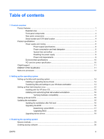 3
3 -
 4
4 -
 5
5 -
 6
6 -
 7
7 -
8
-
9
-
10
-
11
-
12
-
13
-
14
-
15
-
16
-
17
-
18
-
19
-
20
-
21
-
22
-
23
-
24
-
25
-
26
-
27
-
28
-
29
-
30
-
31
-
32
-
33
-
34
-
35
-
36
-
37
-
38
-
39
-
40
-
41
-
42
-
43
-
44
-
45
-
46
-
47
-
48
-
49
-
50
-
51
-
52
-
53
-
54
-
55
-
56
-
57
-
58
-
59
-
60
-
61
-
62
-
63
-
64
-
65
-
66
-
67
-
68
-
69
-
70
-
71
-
72
-
73
-
74
-
75
-
76
-
77
-
78
-
79
-
80
-
81
-
82
-
83
-
84
-
85
-
86
-
87
-
88
-
89
-
90
-
91
-
92
-
93
-
94
-
95
-
96
-
97
-
98
-
99
-
100
-
101
-
102
-
103
-
104
-
105
-
106
-
107
-
108
-
109
-
110
-
111
-
112
-
113
-
114
-
115
-
116
-
117
-
118
-
119
-
120
-
121
-
122
-
123
-
124
-
125
-
126
-
127
-
128
-
129
-
130
-
131
-
132
-
133
-
134
-
135
-
136
-
137
-
138
-
139
-
140
-
141
-
142
-
143
-
144
-
145
-
146
-
147
-
148
-
149
-
150
-
151
-
152
-
153
-
154
-
155
-
156
-
157
-
158
-
159
-
160
-
161
-
162
-
163
-
164
-
165
-
166
-
167
-
168
-
169
-
170
-
171
-
172
-
173
-
174
-
175
-
176
-
177
-
178
-
179
-
180
-
181
-
182
-
183
-
184
-
185
-
186
-
187
-
188
-
189
-
190
-
191
-
192
-
193
-
194
-
195
-
196
-
197
-
198
-
199
-
200
-
201
-
202
-
203
-
204
-
205
-
206
-
207
-
208
-
209
-
210
-
211
-
212
-
213
-
214
-
215
-
216
-
217
-
218
-
219
-
220
-
221
 |
 |

HP xw9400 Workstation Service and Technical
Reference Guide