Maytag MAH5500BWW Service Manual - Page 145
DRIVE MOTOR, Motor Control Access, MOTOR CONTROL BOARD
 |
View all Maytag MAH5500BWW manuals
Add to My Manuals
Save this manual to your list of manuals |
Page 145 highlights
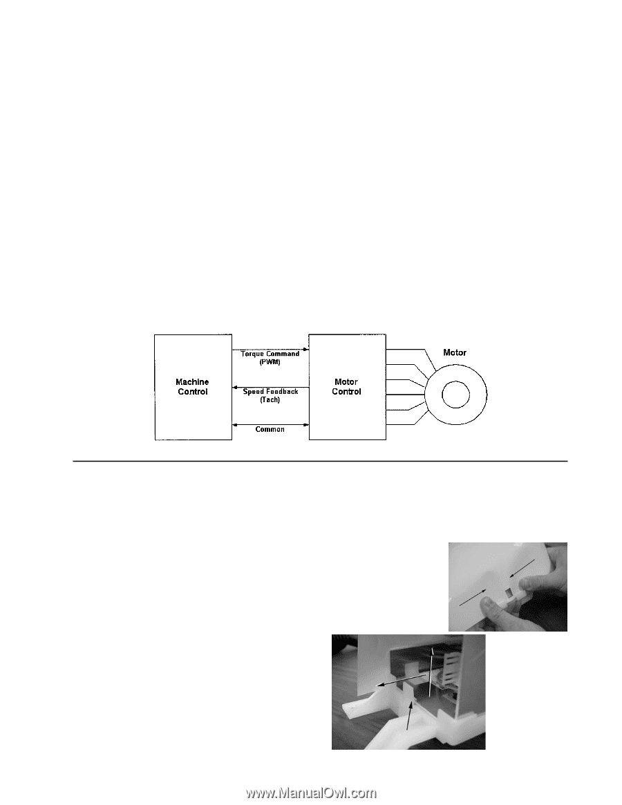
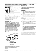
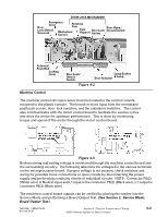
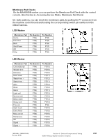
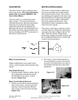
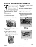
DRIVE MOTOR The drive motor is still a switched reluctance type motor. (For more information, please refer to manual 16008373, Section 4; Drive Motor.) The new motor is a sensorless motor drive system. The word "sensorless" indicates that motor direction and speed detection are performed electrically without the aid of the sending device. Meaning, the sensor was eliminated from the end of the motor along with the wire harness leading to the RPT connection on the motor control board. MOTOR CONTROL BOARD The motor control is able to determine the motor's position by monitoring the active phases in the motor. This is done by sending pulse signals to the motor and then timing the echo signal. By doing this, the motor control is able to deterimine the motor speed and direction. This information is then calculated to determine the motor speed. The motor control has a software switch in it that will turn off all power devices for as long as the main voltage is above 133 VAC. Once the mains voltage drops below that voltage, the power devices will be re-enabled and the motor control will resume normal operation. Motor Control Access Slight modifications were made to the motor control bracket and the plastic drip shield. Drip Shield Removal 1. Push the plastic shield on either side of the locking tab to buckle and unlock the shield from the motor control bracket. (Figure 4-4) Motor Control Board Removal 1. Pull the vertical tab forward and lift the front of the motor control board and slide the control forward to lift and remove the control from the bracket. (Figure 4-5) 2. The motor control board bracket is secured with two screws in front and secured to the baseframe via a tab on the bracket inserted into a slot in the baseframe. Figure 4-4 Figure 4-5 16010486 (16008373-05) Revised 02/01 Section 4. Electrical Components & Testing ©2001 Maytag Appliances Sales Company 4-5
-
 1
1 -
2
-
3
-
4
-
5
-
6
-
7
-
8
-
9
-
10
-
11
-
12
-
13
-
14
-
15
-
16
-
17
-
18
-
19
-
20
-
21
-
22
-
23
-
24
-
25
-
26
-
27
-
28
-
29
-
30
-
31
-
32
-
33
-
34
-
35
-
36
-
37
-
38
-
39
-
40
-
41
-
42
-
43
-
44
-
45
-
46
-
47
-
48
-
49
-
50
-
51
-
52
-
53
-
54
-
55
-
56
-
57
-
58
-
59
-
60
-
61
-
62
-
63
-
64
-
65
-
66
-
67
-
68
-
69
-
70
-
71
-
72
-
73
-
74
-
75
-
76
-
77
-
78
-
79
-
80
-
81
-
82
-
83
-
84
-
85
-
86
-
87
-
88
-
89
-
90
-
91
-
92
-
93
-
94
-
95
-
96
-
97
-
98
-
99
-
100
-
101
-
102
-
103
-
104
-
105
-
106
-
107
-
108
-
109
-
110
-
111
-
112
-
113
-
114
-
115
-
116
-
117
-
118
-
119
-
120
-
121
-
122
-
123
-
124
-
125
-
126
-
127
-
128
-
129
-
130
-
131
-
132
-
133
-
134
-
135
-
136
-
137
-
138
-
139
-
 140
140 -
 141
141 -
 142
142 -
 143
143 -
 144
144 -
 145
145 -
 146
146 -
 147
147 -
 148
148 -
 149
149 -
 150
150 -
151
-
152
-
153
-
154
-
155
-
156
-
157
 |
 |