Maytag MAH5500BWW Service Manual - Page 69
Drive Pulley - outer tub assembly
 |
View all Maytag MAH5500BWW manuals
Add to My Manuals
Save this manual to your list of manuals |
Page 69 highlights
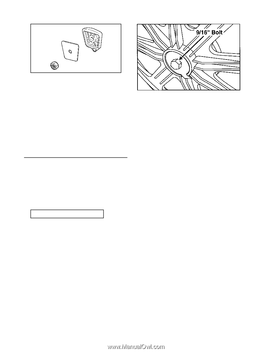
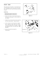
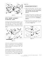
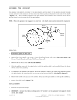
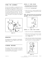
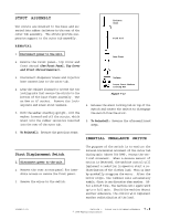
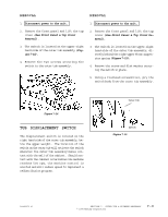
Spinner Support Washer Profile Washer Locking Nut Figure 7-5 5. Remove the spin basket by lifting it off the threaded bolts of the spinner support. 6. When replacing the spin basket onto the spinner support, replace the washers under the three locking type nuts. Secure the ½" nuts firmly (18 in. lbs. torque). Figure 7-6 REPLACEMENT 1. Slide pulley on shaft. 2. Insert new tabbed washer and secure the bolt with a 9/16" socketed ratchet wrench (30 in. lbs. torque). DRIVE PULLEY The drive pulley can be accessed via the rear access panel of the washer. The pulley is secured to the shaft of the spider assembly by a bolt. The direction of pulley rotation controls the spin action of the spin basket. NOTE: If the washer is cupped, flip the washer on the pulley so the cupped portion extends away from the shaft. Failure to do so can result in a binding of the spinner support shaft and seals. 1. Disconnect power to the unit. 2. Remove the rear access panel from the washer to access the pulley area. 3. Remove the bolt and the spider shaft will be exposed. Carefully slide the pulley off the spider shaft, using a "rocking/side-toside" motion. If the pulley has a snug fit, use your Spanner Wrench to apply enough leverage to pry the pulley off the shaft (Figure 7-6). 16008373-01 SECTION 7. OUTER TUB & SPINNER ASSEMBLY 7 - 4 © 1998 Maytag Corporation
-
 1
1 -
2
-
3
-
4
-
5
-
6
-
7
-
8
-
9
-
10
-
11
-
12
-
13
-
14
-
15
-
16
-
17
-
18
-
19
-
20
-
21
-
22
-
23
-
24
-
25
-
26
-
27
-
28
-
29
-
30
-
31
-
32
-
33
-
34
-
35
-
36
-
37
-
38
-
39
-
40
-
41
-
42
-
43
-
44
-
45
-
46
-
47
-
48
-
49
-
50
-
51
-
52
-
53
-
54
-
55
-
56
-
57
-
58
-
59
-
60
-
61
-
62
-
63
-
 64
64 -
 65
65 -
 66
66 -
 67
67 -
 68
68 -
 69
69 -
 70
70 -
 71
71 -
 72
72 -
 73
73 -
 74
74 -
75
-
76
-
77
-
78
-
79
-
80
-
81
-
82
-
83
-
84
-
85
-
86
-
87
-
88
-
89
-
90
-
91
-
92
-
93
-
94
-
95
-
96
-
97
-
98
-
99
-
100
-
101
-
102
-
103
-
104
-
105
-
106
-
107
-
108
-
109
-
110
-
111
-
112
-
113
-
114
-
115
-
116
-
117
-
118
-
119
-
120
-
121
-
122
-
123
-
124
-
125
-
126
-
127
-
128
-
129
-
130
-
131
-
132
-
133
-
134
-
135
-
136
-
137
-
138
-
139
-
140
-
141
-
142
-
143
-
144
-
145
-
146
-
147
-
148
-
149
-
150
-
151
-
152
-
153
-
154
-
155
-
156
-
157
 |
 |