Maytag MAH5500BWW Service Manual - Page 74
Tub Displacement Switch
 |
View all Maytag MAH5500BWW manuals
Add to My Manuals
Save this manual to your list of manuals |
Page 74 highlights
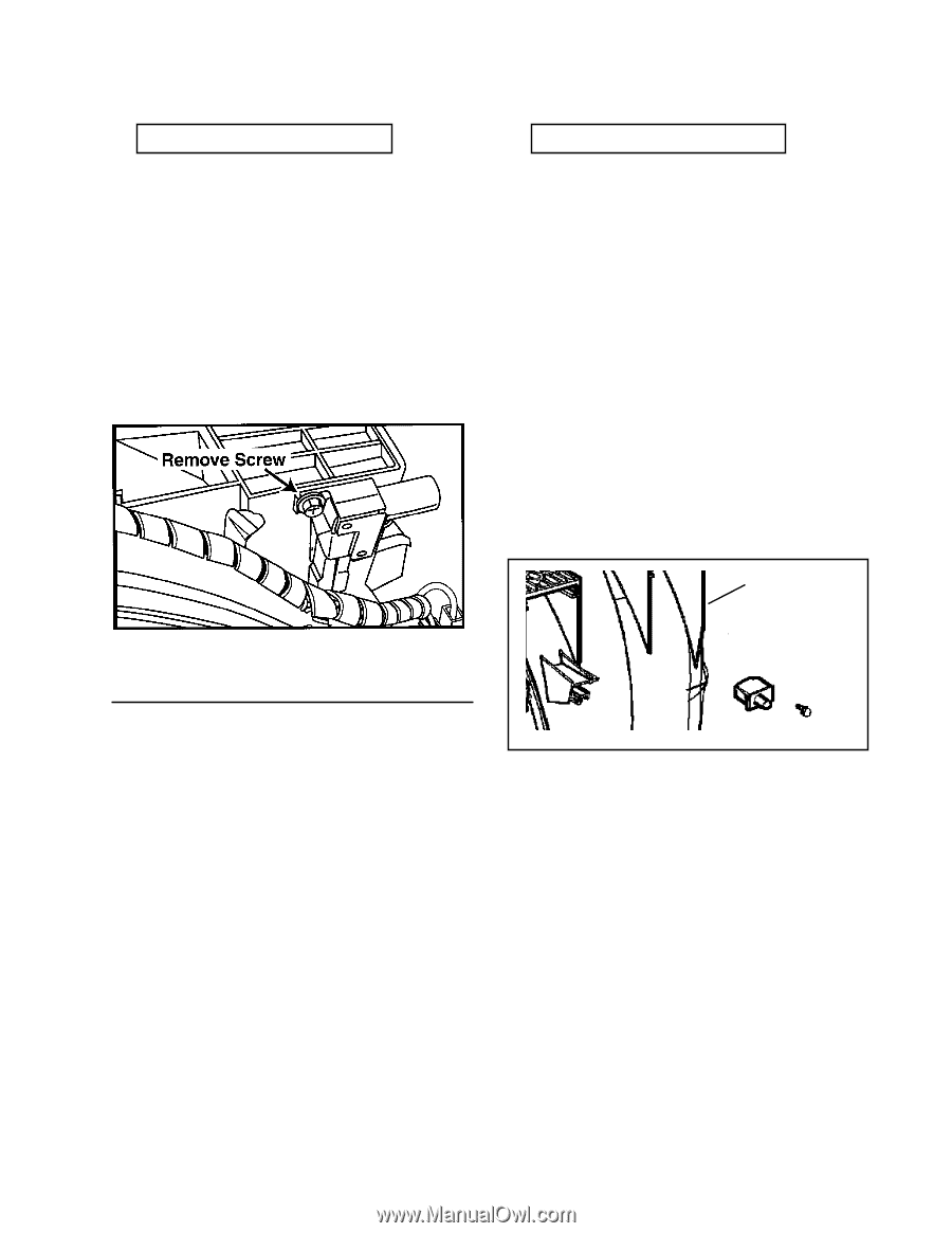
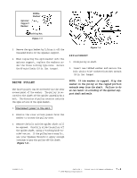
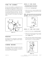
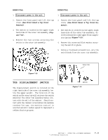
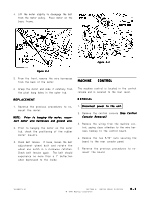
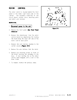
REMOVAL REMOVAL 1. Disconnect power to the unit. 1. Disconnect power to the unit. 2. Remove the front panel and lift the top cover (See Front Panel & Top Cover Removal). 2. Remove the front panel and lift the top cover (See Front Panel & Top Cover Removal). 3. The switch is located on the upper right hand side of the outer tub assembly (Figure 7-14). 4. Remove the two screws securing the switch to the outer tub assembly. 3. The switch is located on the upper right hand side of the outer tub assembly, directly behind the right upper front suspension spring (Figure 7-15). 4. Remove the screw and flat washer securing the switch in place. 5. Using a flathead screwdriver, pry the switch body from the outer tub assembly. Figure 7-14 TUB DISPLACEMENT SWITCH The displacement switch is located on the right hand side of the outer tub assembly, below the upper weight. The location of the switch on the outer tub will activate the switch whenever the outer tub assembly makes contact with the wall of the cabinet. Should contact with the cabinet occur before the machine reaches 500 rpm, the machine control is alerted and will reduce speed to implement a redistribution program. Outer Tub Switch Figure 7-15 16008373-01 SECTION 7. OUTER TUB & SPINNER ASSEMBLY © 1998 Maytag Corporation 7-9
-
 1
1 -
2
-
3
-
4
-
5
-
6
-
7
-
8
-
9
-
10
-
11
-
12
-
13
-
14
-
15
-
16
-
17
-
18
-
19
-
20
-
21
-
22
-
23
-
24
-
25
-
26
-
27
-
28
-
29
-
30
-
31
-
32
-
33
-
34
-
35
-
36
-
37
-
38
-
39
-
40
-
41
-
42
-
43
-
44
-
45
-
46
-
47
-
48
-
49
-
50
-
51
-
52
-
53
-
54
-
55
-
56
-
57
-
58
-
59
-
60
-
61
-
62
-
63
-
64
-
65
-
66
-
67
-
68
-
 69
69 -
 70
70 -
 71
71 -
 72
72 -
 73
73 -
 74
74 -
 75
75 -
 76
76 -
 77
77 -
 78
78 -
 79
79 -
80
-
81
-
82
-
83
-
84
-
85
-
86
-
87
-
88
-
89
-
90
-
91
-
92
-
93
-
94
-
95
-
96
-
97
-
98
-
99
-
100
-
101
-
102
-
103
-
104
-
105
-
106
-
107
-
108
-
109
-
110
-
111
-
112
-
113
-
114
-
115
-
116
-
117
-
118
-
119
-
120
-
121
-
122
-
123
-
124
-
125
-
126
-
127
-
128
-
129
-
130
-
131
-
132
-
133
-
134
-
135
-
136
-
137
-
138
-
139
-
140
-
141
-
142
-
143
-
144
-
145
-
146
-
147
-
148
-
149
-
150
-
151
-
152
-
153
-
154
-
155
-
156
-
157
 |
 |