Maytag MAH5500BWW Service Manual - Page 25
Machine Control - motor control board
 |
View all Maytag MAH5500BWW manuals
Add to My Manuals
Save this manual to your list of manuals |
Page 25 highlights
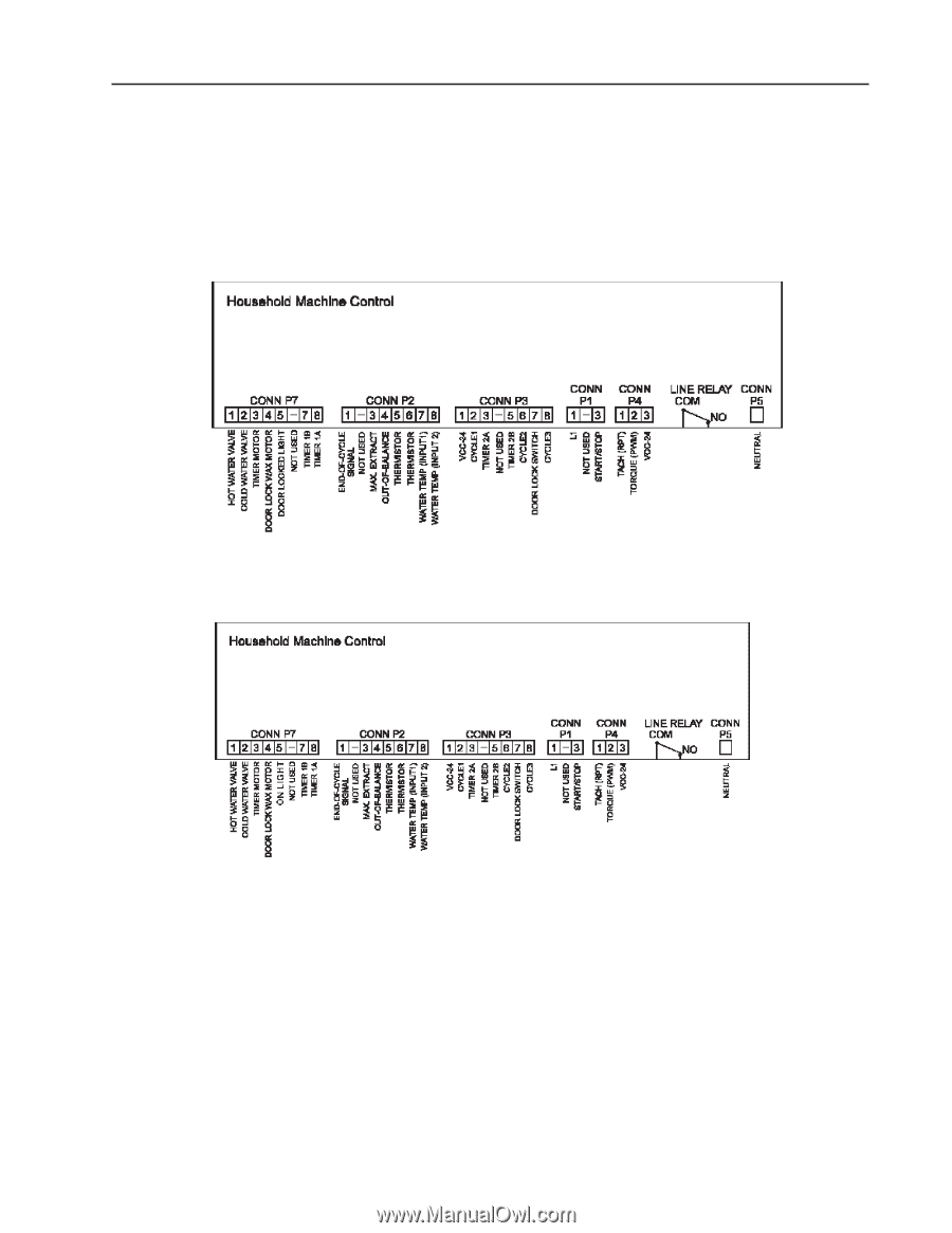
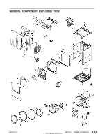
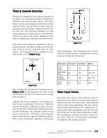
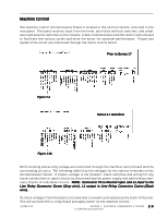
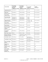
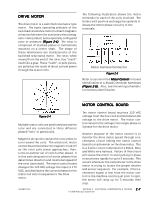
Machine Control The machine control microprocessor board is located in the control console, mounted to the rear panel. The board receives input from the timer, door latch and lock switches, and unbalance and selector switches on the console. It also communicates with the motor control board to facilitate the various cycles and drive the motor for optimum performance. Torque and speed of the motor are monitored through the motor control board. Prior to Series 17 Figure 2-3 Series 17 and After Figure 2-3b Both incoming and exiting voltage are monitored through the machine control board and the surrounding circuitry. The following table lists the voltages for the various terminals on the microprocessor board. If proper voltage is not present, check switches and wiring for any loose connections or open circuits by disconnecting the power supply and performing continuity checks of individual circuits. NOTE: Connector P5 is Neutral input and L1 input is the Line Relay Connector Comm (Gray wire), L1 output is Line Relay Connector Comm (Black wire). To check voltages from the board, turn timer dial to a wash cycle and press the start/off button. This will activate the L1 relay board and apply power on the machine control. 16008373-01 SECTION 2. ELECTRICAL COMPONENTS & TESTING 2 - 5 © 1998 Maytag Corporation
-
 1
1 -
2
-
3
-
4
-
5
-
6
-
7
-
8
-
9
-
10
-
11
-
12
-
13
-
14
-
15
-
16
-
17
-
18
-
19
-
 20
20 -
 21
21 -
 22
22 -
 23
23 -
 24
24 -
 25
25 -
 26
26 -
 27
27 -
 28
28 -
 29
29 -
 30
30 -
31
-
32
-
33
-
34
-
35
-
36
-
37
-
38
-
39
-
40
-
41
-
42
-
43
-
44
-
45
-
46
-
47
-
48
-
49
-
50
-
51
-
52
-
53
-
54
-
55
-
56
-
57
-
58
-
59
-
60
-
61
-
62
-
63
-
64
-
65
-
66
-
67
-
68
-
69
-
70
-
71
-
72
-
73
-
74
-
75
-
76
-
77
-
78
-
79
-
80
-
81
-
82
-
83
-
84
-
85
-
86
-
87
-
88
-
89
-
90
-
91
-
92
-
93
-
94
-
95
-
96
-
97
-
98
-
99
-
100
-
101
-
102
-
103
-
104
-
105
-
106
-
107
-
108
-
109
-
110
-
111
-
112
-
113
-
114
-
115
-
116
-
117
-
118
-
119
-
120
-
121
-
122
-
123
-
124
-
125
-
126
-
127
-
128
-
129
-
130
-
131
-
132
-
133
-
134
-
135
-
136
-
137
-
138
-
139
-
140
-
141
-
142
-
143
-
144
-
145
-
146
-
147
-
148
-
149
-
150
-
151
-
152
-
153
-
154
-
155
-
156
-
157
 |
 |