Maytag MAH5500BWW Service Manual - Page 67
Outer Tub Cover - door gasket
 |
View all Maytag MAH5500BWW manuals
Add to My Manuals
Save this manual to your list of manuals |
Page 67 highlights
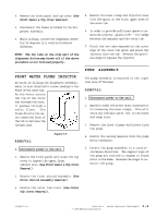
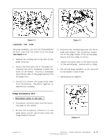
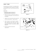
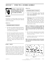
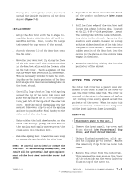
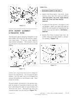
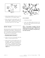
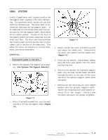
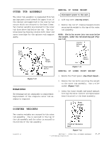
6. Unsnap the locking tabs of the door boot around the inside perimeter of the door shroud (Figure 7-1). REPLACEMENT 1. Align the door boot with the D-shape toward the front, with the flat of the D toward the bottom. Also, locate the large tab toward the top center of the shroud. 2. Stretch the rear lip of the door boot onto the tub cover. 3. Move the rear door boot lip along the face of the tub cover until the locator notches in the door boot align with the locator ribs in the tub cover. Check alignment of the six rib marks and reposition if necessary. This is necessary in order to have the locking tabs on the inside perimeter of the door boot align with the corresponding tabs on the front shroud. 4. Carefully loop the wire loop with spring around the lip of the outer tub cover and place the spring at the 11:00 o'clock position, just left of the top rib of the outer tub cover. Hook the end of the spring over the nearest tub cover clip to hold the spring and wire in position for final hookup to the other end of the wire loop. 5. Using either the hold down bracket or the outer tub spring, grasp the hook end of the spring and apply pressure on the clamp wire into the door boot. 6. Pull the spring hook toward the wire loop to engage the spring with the wire loop. NOTE: Be careful not to bend or crease the wire loop. If the wire loop becomes bent, the result will be a potential leak upon replacement of the boot seal onto the outer tub cover. 7. Reposition the front shroud on the front of the washer and secure (See Front Shroud). 8. Pull the front edge of the door boot and locate the widest locking tabs, located at the 12, 4 & 8 o'clock positions. Insert the locking tabs into the large interlocking slots in the shroud. (Spraying the surface with window cleaner or a soap solution aids reinsertion of the tabs into the plastic front shroud.) Press the thick rubber section of the door boot into the groove in the shroud so the locking tabs engage in the slots. 9. Press the remaining locking tabs into the perimeter of the shroud. OUTER TUB COVER The outer tub cover has a gasket seal embedded in the outer flange of the cover to seal the cover to the outer tub. The cover is secured to the outer tub by means of twelve (12) locking clips evenly spaced around the perimeter of the cover. When the outer tub cover is removed, access to the sump area and the front injector flume is possible. REMOVAL 1. Disconnect power to the unit. 2. Remove the front panel, top cover and front shroud (See Front Panel, Top Cover, and Front Shroud Removal). 3. Using a flathead screwdriver, slide under the clip and pry to remove. Remove the remaining clips from the outer tub cover. 4. Remove the cover from the outer tub. This exposes the sump area on the floor of the outer tub and the water injector flume on top of the outer tub. 16008373-01 SECTION 7. OUTER TUB & SPINNER ASSEMBLY 7 - 2 © 1998 Maytag Corporation
-
 1
1 -
2
-
3
-
4
-
5
-
6
-
7
-
8
-
9
-
10
-
11
-
12
-
13
-
14
-
15
-
16
-
17
-
18
-
19
-
20
-
21
-
22
-
23
-
24
-
25
-
26
-
27
-
28
-
29
-
30
-
31
-
32
-
33
-
34
-
35
-
36
-
37
-
38
-
39
-
40
-
41
-
42
-
43
-
44
-
45
-
46
-
47
-
48
-
49
-
50
-
51
-
52
-
53
-
54
-
55
-
56
-
57
-
58
-
59
-
60
-
61
-
 62
62 -
 63
63 -
 64
64 -
 65
65 -
 66
66 -
 67
67 -
 68
68 -
 69
69 -
 70
70 -
 71
71 -
 72
72 -
73
-
74
-
75
-
76
-
77
-
78
-
79
-
80
-
81
-
82
-
83
-
84
-
85
-
86
-
87
-
88
-
89
-
90
-
91
-
92
-
93
-
94
-
95
-
96
-
97
-
98
-
99
-
100
-
101
-
102
-
103
-
104
-
105
-
106
-
107
-
108
-
109
-
110
-
111
-
112
-
113
-
114
-
115
-
116
-
117
-
118
-
119
-
120
-
121
-
122
-
123
-
124
-
125
-
126
-
127
-
128
-
129
-
130
-
131
-
132
-
133
-
134
-
135
-
136
-
137
-
138
-
139
-
140
-
141
-
142
-
143
-
144
-
145
-
146
-
147
-
148
-
149
-
150
-
151
-
152
-
153
-
154
-
155
-
156
-
157
 |
 |
