Maytag MAH5500BWW Service Manual - Page 60
Air Dome Hose, Water Level Pressure, Switch
 |
View all Maytag MAH5500BWW manuals
Add to My Manuals
Save this manual to your list of manuals |
Page 60 highlights
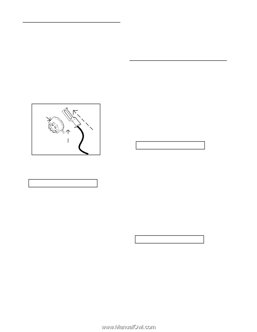
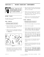
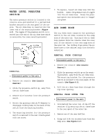
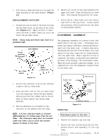
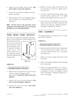
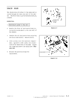
WATER LEVEL PRESSURE SWITCH The water pressure switch is located in the console area and mounted to a galvanized bracket secured to the rear panel of the console. The air dome hose is inserted into the lower end of the mounting bracket (Figure 6-2). The nipple of the pressure switch is inserted into the end of the air dome hose which is secured by the lower mounting bracket. Bracket Pressure Switch A) Slide Switch Off 7. To replace, insert air dome hose into the bracket. Insert the pressure switch nipple into the air dome hose. Press the pressure switch into the bracket until it "snaps" into place. AIR DOME HOSE The air dome hose connects the pressure switch to the air dome located in the sump area of the outer tub. Routing of the air dome hose passes from the console down the rear wall of the cabinet to the rear sump area of the outer tub. Two holding clips retain the air dome hose to the cabinet away from the belt and pulley. B) Rotate Switch Air Dome Hose Figure 6-2 REMOVAL 1. Disconnect power to the unit. 2. Remove the console (See Console Removal). 3. Slide the pressure switch up, away from the air dome hose. 4. Remove wire harness from the pressure switch. 5. Rotate the pressure switch 90 degrees to disengage locking tabs on the back of the switch from the mounting bracket. 6. The mounting bracket for the pressure switch is secured to the rear console panel with one screw. REMOVAL FROM CONSOLE 1. Disconnect power to the unit. 2. Remove the console (See Console Removal). 3. Slide the pressure switch up on the mounting bracket, away from the air dome hose. The mounting bracket for the pressure switch is secured to the rear panel of the console (See Figure 6-2). 4. Pull the air dome hose down through the top cover opening. REMOVAL FROM OUTER TUB 1. Disconnect power to the unit. 2. From behind the outer tub, slide off the retainer clip securing the air dome hose to the rear spout of the outer tub. 3. Remove one of the rear baffles. 4. Grasp and lift the airdome hose from the sump area (See Figure 6-3). 16008373-01 SECTION 6. WATER CARRYING COMPONENTS 6-2 © 1998 Maytag Corporation
-
 1
1 -
2
-
3
-
4
-
5
-
6
-
7
-
8
-
9
-
10
-
11
-
12
-
13
-
14
-
15
-
16
-
17
-
18
-
19
-
20
-
21
-
22
-
23
-
24
-
25
-
26
-
27
-
28
-
29
-
30
-
31
-
32
-
33
-
34
-
35
-
36
-
37
-
38
-
39
-
40
-
41
-
42
-
43
-
44
-
45
-
46
-
47
-
48
-
49
-
50
-
51
-
52
-
53
-
54
-
 55
55 -
 56
56 -
 57
57 -
 58
58 -
 59
59 -
 60
60 -
 61
61 -
 62
62 -
 63
63 -
 64
64 -
 65
65 -
66
-
67
-
68
-
69
-
70
-
71
-
72
-
73
-
74
-
75
-
76
-
77
-
78
-
79
-
80
-
81
-
82
-
83
-
84
-
85
-
86
-
87
-
88
-
89
-
90
-
91
-
92
-
93
-
94
-
95
-
96
-
97
-
98
-
99
-
100
-
101
-
102
-
103
-
104
-
105
-
106
-
107
-
108
-
109
-
110
-
111
-
112
-
113
-
114
-
115
-
116
-
117
-
118
-
119
-
120
-
121
-
122
-
123
-
124
-
125
-
126
-
127
-
128
-
129
-
130
-
131
-
132
-
133
-
134
-
135
-
136
-
137
-
138
-
139
-
140
-
141
-
142
-
143
-
144
-
145
-
146
-
147
-
148
-
149
-
150
-
151
-
152
-
153
-
154
-
155
-
156
-
157
 |
 |