Maytag MAH5500BWW Service Manual - Page 50

VERTICAL, SWITCHES, Push Button, HORIZONTAL, Push-to-Start - replacement parts

Page 50 highlights

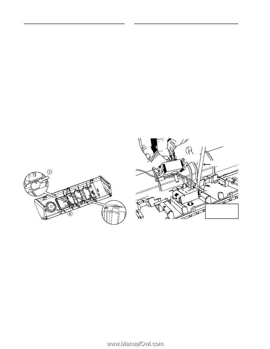
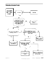
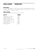
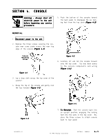
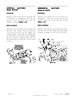
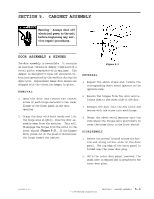
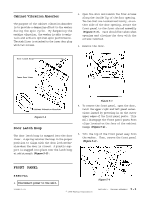
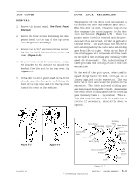
VERTICAL SWITCHES (Push Button) REMOVAL HORIZONTAL SWITCHES (Push-to-Start) REMOVAL Depress the tab at the top of the switch with a screwdriver to disengage the tab from the console. Pivot the switch away from the console to remove (Figure 4-5). Depress the locking tab on the switch to disengage it from the locking tab on the console. Pivot the switch from the console (Figure 4-6). REPLACEMENT REPLACEMENT Align the rib on the bottom of the switch with the slot in the console. Pivot the switch up into the console until the tab engages the console securely. Check that the locating tabs on either side of the switch's lower alignment rib are in position to properly center and lock the switch into the lower part of the switch opening. Position one side into the console and pivot the other tab into the console and apply enough pressure to engage the tab into the console. Align the Center Rib on the bottom of the Switch with the Slot in the Cup on the Bottom of the Switch Opening on the Console Locking Tab Locking Tab Screwdriver Locking Tab Locking Tab Figure 4-5 Pivoting the Switch Body, Lock it in at the Top of the Opening on the Console. Figure 4-6 Carefully Depress Locking Tab on Switch to Disengage From Console 16008373-01 © 1998 Maytag Corporation SECTION 4. CONSOLE 4 - 2

  • 1
  • 2
  • 3
  • 4
  • 5
  • 6
  • 7
  • 8
  • 9
  • 10
  • 11
  • 12
  • 13
  • 14
  • 15
  • 16
  • 17
  • 18
  • 19
  • 20
  • 21
  • 22
  • 23
  • 24
  • 25
  • 26
  • 27
  • 28
  • 29
  • 30
  • 31
  • 32
  • 33
  • 34
  • 35
  • 36
  • 37
  • 38
  • 39
  • 40
  • 41
  • 42
  • 43
  • 44
  • 45
  • 46
  • 47
  • 48
  • 49
  • 50
  • 51
  • 52
  • 53
  • 54
  • 55
  • 56
  • 57
  • 58
  • 59
  • 60
  • 61
  • 62
  • 63
  • 64
  • 65
  • 66
  • 67
  • 68
  • 69
  • 70
  • 71
  • 72
  • 73
  • 74
  • 75
  • 76
  • 77
  • 78
  • 79
  • 80
  • 81
  • 82
  • 83
  • 84
  • 85
  • 86
  • 87
  • 88
  • 89
  • 90
  • 91
  • 92
  • 93
  • 94
  • 95
  • 96
  • 97
  • 98
  • 99
  • 100
  • 101
  • 102
  • 103
  • 104
  • 105
  • 106
  • 107
  • 108
  • 109
  • 110
  • 111
  • 112
  • 113
  • 114
  • 115
  • 116
  • 117
  • 118
  • 119
  • 120
  • 121
  • 122
  • 123
  • 124
  • 125
  • 126
  • 127
  • 128
  • 129
  • 130
  • 131
  • 132
  • 133
  • 134
  • 135
  • 136
  • 137
  • 138
  • 139
  • 140
  • 141
  • 142
  • 143
  • 144
  • 145
  • 146
  • 147
  • 148
  • 149
  • 150
  • 151
  • 152
  • 153
  • 154
  • 155
  • 156
  • 157

© 1998 Maytag Corporation
16008373-01
SECTION 4.
CONSOLE
4-2
4-2
4-2
4-2
4-2
REMOVAL
REMOVAL
REMOVAL
REMOVAL
REMOVAL
Depress the tab at the top of the switch with
a screwdriver to disengage the tab from the
console.
Pivot the switch away from the
console to remove
(Figure 4-5)
(Figure 4-5)
(Figure 4-5)
(Figure 4-5)
(Figure 4-5)
.
REPLACEMENT
REPLACEMENT
REPLACEMENT
REPLACEMENT
REPLACEMENT
Align the rib on the bottom of the switch with
the slot in the console.
Pivot the switch up
into the console until the tab engages the
console securely.
Check that the locating tabs
on either side of the switch's lower alignment
rib are in position to properly center and lock
the switch into the lower part of the switch
opening.
VERTICAL
SWITCHES
VERTICAL
SWITCHES
VERTICAL
SWITCHES
VERTICAL
SWITCHES
VERTICAL
SWITCHES
(Push Button)
(Push Button)
(Push Button)
(Push Button)
(Push Button)
HORIZONTAL
SWITCHES
HORIZONTAL
SWITCHES
HORIZONTAL
SWITCHES
HORIZONTAL
SWITCHES
HORIZONTAL
SWITCHES
(Push-to-Start)
(Push-to-Start)
(Push-to-Start)
(Push-to-Start)
(Push-to-Start)
Locking Tab
Locking Tab
Locking Tab
Screwdriver
Locking Tab
Carefully Depress
Carefully Depress
Carefully Depress
Carefully Depress
Carefully Depress
Locking Tab on
Locking Tab on
Locking Tab on
Locking Tab on
Locking Tab on
Switch to Disengage
Switch to Disengage
Switch to Disengage
Switch to Disengage
Switch to Disengage
From Console
From Console
From Console
From Console
From Console
Figure 4-6
Figure 4-6
Figure 4-6
Figure 4-6
Figure 4-6
Figure 4-5
Figure 4-5
Figure 4-5
Figure 4-5
Figure 4-5
Align the Center Rib
on the bottom of the
Switch with the Slot in
the Cup on the Bottom
of the Switch Opening
on the Console
on the Console
on the Console
on the Console
on the Console
Pivoting the
Pivoting the
Pivoting the
Pivoting the
Pivoting the
Switch Body, Lock
Switch Body, Lock
Switch Body, Lock
Switch Body, Lock
Switch Body, Lock
it in at the Top of
it in at the Top of
it in at the Top of
it in at the Top of
it in at the Top of
the Opening
the Opening
the Opening
the Opening
the Opening
on the Console.
on the Console.
on the Console.
on the Console.
on the Console.
REMOVAL
REMOVAL
REMOVAL
REMOVAL
REMOVAL
Depress the locking tab on the switch to
disengage it from the locking tab on the
console.
Pivot the switch from the console
(Figure 4-6).
(Figure 4-6).
(Figure 4-6).
(Figure 4-6).
(Figure 4-6).
REPLACEMENT
REPLACEMENT
REPLACEMENT
REPLACEMENT
REPLACEMENT
Position one side into the console and pivot
the other tab into the console and apply enough
pressure to engage the tab into the console.