Maytag MAH5500BWW Service Manual - Page 61
Dispenser Assembly - leaking
 |
View all Maytag MAH5500BWW manuals
Add to My Manuals
Save this manual to your list of manuals |
Page 61 highlights
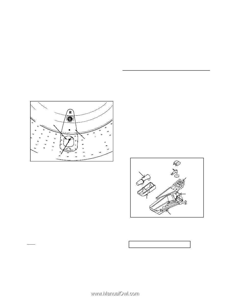
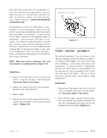
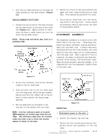
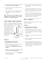
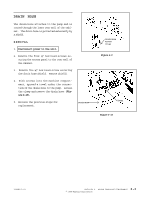
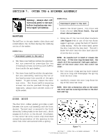
5. Pull the air dome and hose out through the sump opening in the spin basket (Figure 6-3). 5. Remove all slack in the hose between the upper and lower clips holding the air dome hose. This reduces the potential for noise. REPLACEMENT/ROUTING 1. Thread the narrow end of the hose through the air dome outlet in the rear of the outer tub (Figure 6-3). Apply alcohol to lubricate the hose to ease insertion into the outer tub air dome outlet. 6. Route the air dome hose into the center rear hole in the top cover. Route toward the pressure switch and secure the hose to the pressure switch. DISPENSER ASSEMBLY NOTE: Using soap and water may lead to a potential leak. Sump Opening Exposed Spin Basket Air Dome Outlet Figure 6-3 Rear Baffle Removed 2. Secure the retainer clip on the outside ridge of the air dome hose. The dispenser assembly is located in the left hand side of the top cover. Three bays dispense the fabric softener, bleach and detergent into the wash load. A double wax motor mechanism directs the flow of water into each specific bay when required for disbursement into the wash load. When a specific fluid is required, the water is directed into that bay. As water fills the bay, the fluid level rises. When the fluid reaches a specific height, it is siphoned out into the dispenser injector hose to the wash load. Siphon Cap Linkage Wax Motors Dispenser Top 3. Push the bent end of the air dome down into the sump area, below the spin basket, making sure the flat rubber tab on the air dome is down inside the drain sump opening. 4. The air dome hose is retained to the rear wall of the cabinet with two clips. Siphon Cup Rotary Nozzle REMOVAL Dispenser Bottom Figure 6-4 NOTE: A silver indicator mark is located approximately 20 inches away from the air dome. The indicator mark must be located under the lower clip to allow the correct amount of slack in the hose. 1. Disconnect power to the unit. 2. Remove the siphon cup and cap. 3. Remove the four screws securing the dispenser bezel and assembly to the top cover. 16008373-01 SECTION 6. WATER CARRYING COMPONENTS © 1998 Maytag Corporation 6-3
-
 1
1 -
2
-
3
-
4
-
5
-
6
-
7
-
8
-
9
-
10
-
11
-
12
-
13
-
14
-
15
-
16
-
17
-
18
-
19
-
20
-
21
-
22
-
23
-
24
-
25
-
26
-
27
-
28
-
29
-
30
-
31
-
32
-
33
-
34
-
35
-
36
-
37
-
38
-
39
-
40
-
41
-
42
-
43
-
44
-
45
-
46
-
47
-
48
-
49
-
50
-
51
-
52
-
53
-
54
-
55
-
 56
56 -
 57
57 -
 58
58 -
 59
59 -
 60
60 -
 61
61 -
 62
62 -
 63
63 -
 64
64 -
 65
65 -
 66
66 -
67
-
68
-
69
-
70
-
71
-
72
-
73
-
74
-
75
-
76
-
77
-
78
-
79
-
80
-
81
-
82
-
83
-
84
-
85
-
86
-
87
-
88
-
89
-
90
-
91
-
92
-
93
-
94
-
95
-
96
-
97
-
98
-
99
-
100
-
101
-
102
-
103
-
104
-
105
-
106
-
107
-
108
-
109
-
110
-
111
-
112
-
113
-
114
-
115
-
116
-
117
-
118
-
119
-
120
-
121
-
122
-
123
-
124
-
125
-
126
-
127
-
128
-
129
-
130
-
131
-
132
-
133
-
134
-
135
-
136
-
137
-
138
-
139
-
140
-
141
-
142
-
143
-
144
-
145
-
146
-
147
-
148
-
149
-
150
-
151
-
152
-
153
-
154
-
155
-
156
-
157
 |
 |