Maytag MAH5500BWW Service Manual - Page 30
Tachometer Cir, achometer Cir, achometer Circuit Diagnostics, cuit Diagnostics - size
 |
View all Maytag MAH5500BWW manuals
Add to My Manuals
Save this manual to your list of manuals |
Page 30 highlights
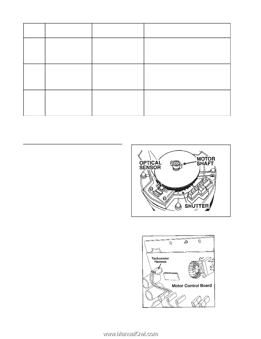
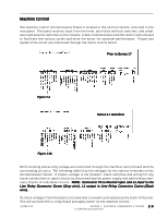
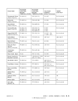
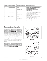
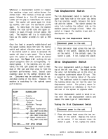
PHASE WIRE COLORS C Yellow or Orange B White or Red A Black or Blue MOTOR CONDITION RESULT/SOLUTION Runs Does Not Run Runs Does Not Run Runs Does Not Run -Phases A&B are operating correctly. (Check Phase A and B) -Phase A or B is non-functional. (See Step 10) -Phases A&C are operating correctly. (Check Phase A and C) -Phase A or C is non-functional. (See Step 10) -Phases B&C are operating correctly. (Check Phase B and C) -Phase B or C is non-functional. (See Step 10) Tachometer Circuit Diagnostics The tachometer system of the motor is comprised of a plastic wheel, called a shutter, and an optical sensor (Figure 2-9). The shutter is mounted to the end of the motor shaft under the plastic endbell covering of the motor. The edge of the shutter resembles a "picket fence" with different size "pickets." The pattern consists of six different "pickets" which are repeated eight times. An optical sensor is mounted to one side of the shutter and monitors the "pickets" as they pass through the sensor. As the "pickets" pass through the sensor field, signals are generated and transmitted to the motor control board through the tachometer wire harness (Figure 2-10 and 2-11). Figure 2-9 16008373-01 Figure 2-10 SECTION 2. ELECTRICAL COMPONENTS & TESTING 2-10 © 1998 Maytag Corporation
-
 1
1 -
2
-
3
-
4
-
5
-
6
-
7
-
8
-
9
-
10
-
11
-
12
-
13
-
14
-
15
-
16
-
17
-
18
-
19
-
20
-
21
-
22
-
23
-
24
-
 25
25 -
 26
26 -
 27
27 -
 28
28 -
 29
29 -
 30
30 -
 31
31 -
 32
32 -
 33
33 -
 34
34 -
 35
35 -
36
-
37
-
38
-
39
-
40
-
41
-
42
-
43
-
44
-
45
-
46
-
47
-
48
-
49
-
50
-
51
-
52
-
53
-
54
-
55
-
56
-
57
-
58
-
59
-
60
-
61
-
62
-
63
-
64
-
65
-
66
-
67
-
68
-
69
-
70
-
71
-
72
-
73
-
74
-
75
-
76
-
77
-
78
-
79
-
80
-
81
-
82
-
83
-
84
-
85
-
86
-
87
-
88
-
89
-
90
-
91
-
92
-
93
-
94
-
95
-
96
-
97
-
98
-
99
-
100
-
101
-
102
-
103
-
104
-
105
-
106
-
107
-
108
-
109
-
110
-
111
-
112
-
113
-
114
-
115
-
116
-
117
-
118
-
119
-
120
-
121
-
122
-
123
-
124
-
125
-
126
-
127
-
128
-
129
-
130
-
131
-
132
-
133
-
134
-
135
-
136
-
137
-
138
-
139
-
140
-
141
-
142
-
143
-
144
-
145
-
146
-
147
-
148
-
149
-
150
-
151
-
152
-
153
-
154
-
155
-
156
-
157
 |
 |