Panasonic VDR M50 Dvd Camcorder - Page 19
Names Of Parts
 |
UPC - 037988251209
View all Panasonic VDR M50 manuals
Add to My Manuals
Save this manual to your list of manuals |
Page 19 highlights
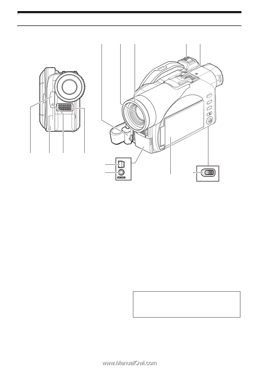
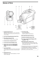
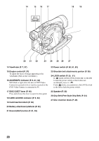
Names of Parts 5 67 89 NAVDIGISACTION SELECT MENU u y t i 1 23 4 10 A/V 11 MIC (Inside the cover) 13 12 BATTERY EJECT (Bottom) 1 Infrared receiver (P. 37) When the remote controller is used to operate the DVD Video Camera, this receiver will receive the infrared signal. 2 Lens cap string attachment hole (P. 35) 3 Recording indicator (P. 93) The red indicator will light during recording. 4 Internal stereo microphone (P. 51) 5 Lock cover and Lock button (P. 34) 6 Optical 10x zoom lens (VDR-M70PP) Optical 18× zoom lens (VDR-M50PP) (P. 57) 7 Lens hood (P. 58) Always remove this lens hood when using optionaluser provided tele-conversion or wide-conversion lens. 9 Hot shoe (P. 68) Only for VDR-M70PP: Attach the optional video flash here. 10 AV input/output jack (P. 69, 75) 11 External microphone jack (P. 68) 12 2.5" type Liquid Crystal Display (LCD) (inside) (P. 7, 38) 13 BATTERY EJECT switch (P. 42) The BATTERY EJECT switch is located on the bottom of this DVD Video Camera: Slide it when removing the battery pack. Although the external appearances of VDR-M50PP and VDR-M70PP are different, the method of operating both models is identical. VDR-M70PP illustrations are used in this manual. 8 Zoom lever (P. 57) Push the lever to the T side for telephoto, or to the W side for wide-angle. 19
-
 1
1 -
2
-
3
-
4
-
5
-
6
-
7
-
8
-
9
-
10
-
11
-
12
-
13
-
 14
14 -
 15
15 -
 16
16 -
 17
17 -
 18
18 -
 19
19 -
 20
20 -
 21
21 -
 22
22 -
 23
23 -
 24
24 -
25
-
26
-
27
-
28
-
29
-
30
-
31
-
32
-
33
-
34
-
35
-
36
-
37
-
38
-
39
-
40
-
41
-
42
-
43
-
44
-
45
-
46
-
47
-
48
-
49
-
50
-
51
-
52
-
53
-
54
-
55
-
56
-
57
-
58
-
59
-
60
-
61
-
62
-
63
-
64
-
65
-
66
-
67
-
68
-
69
-
70
-
71
-
72
-
73
-
74
-
75
-
76
-
77
-
78
-
79
-
80
-
81
-
82
-
83
-
84
-
85
-
86
-
87
-
88
-
89
-
90
-
91
-
92
-
93
-
94
-
95
-
96
-
97
-
98
-
99
-
100
-
101
-
102
-
103
-
104
-
105
-
106
-
107
-
108
-
109
-
110
-
111
-
112
-
113
-
114
-
115
-
116
-
117
-
118
-
119
-
120
-
121
-
122
-
123
-
124
-
125
-
126
-
127
-
128
-
129
-
130
-
131
-
132
-
133
-
134
-
135
-
136
-
137
-
138
-
139
-
140
-
141
-
142
-
143
-
144
-
145
-
146
-
147
-
148
-
149
-
150
-
151
-
152
-
153
-
154
-
155
-
156
-
157
-
158
-
159
-
160
-
161
-
162
-
163
-
164
-
165
-
166
-
167
-
168
-
169
-
170
-
171
-
172
-
173
-
174
 |
 |