Sharp DX-B350P DX-B350P DX-B450P Operation Manual - Page 92
the base plate of the top module.
 |
View all Sharp DX-B350P manuals
Add to My Manuals
Save this manual to your list of manuals |
Page 92 highlights
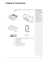
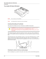
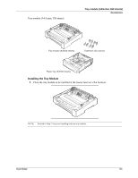
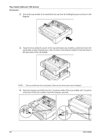
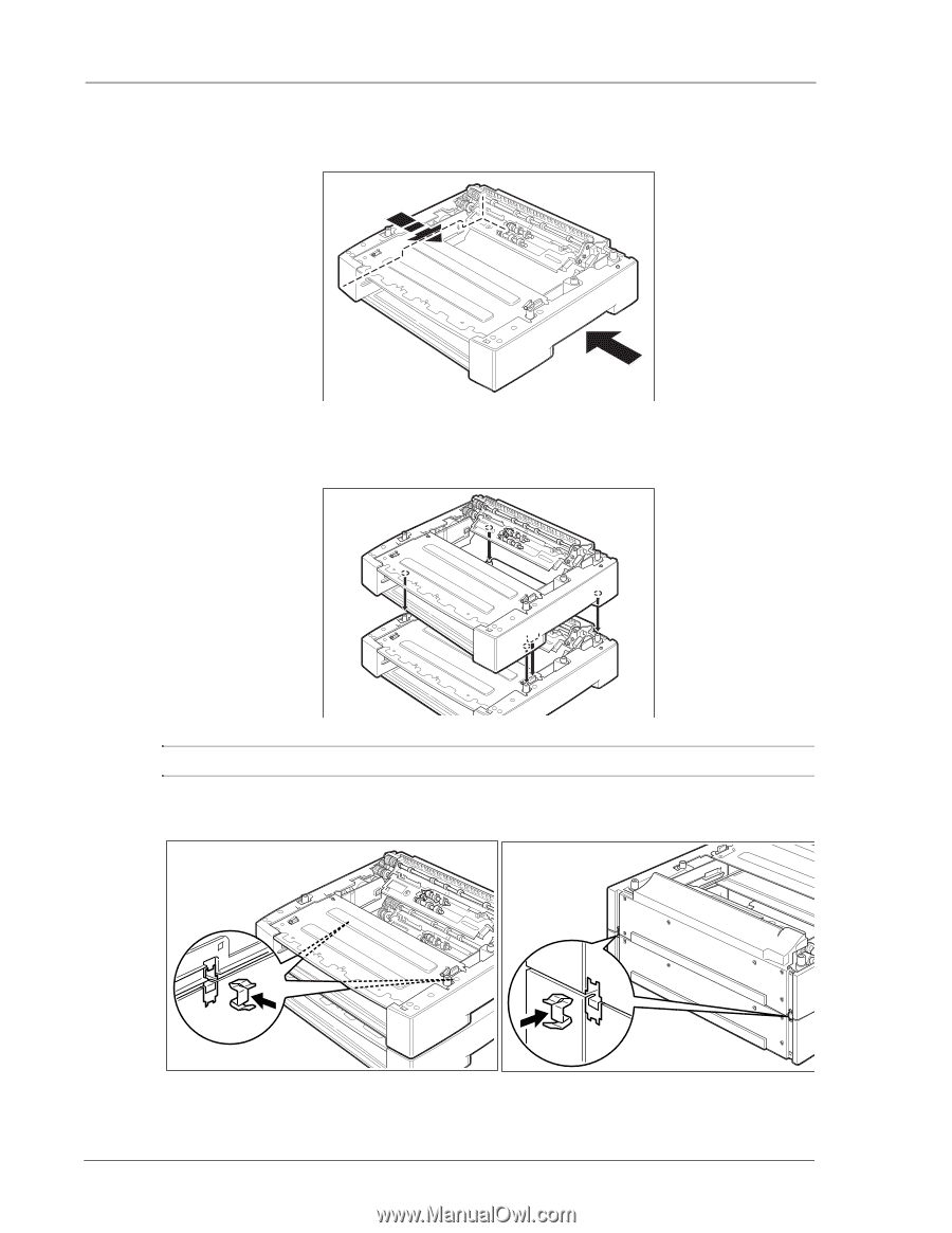
Tray module (A4/Letter, 550 sheets) Accessories 2. Lift up the tray module to be installed at the top level by holding the parts as shown in the diagram. 3. Align the front and back corners of the top and bottom tray modules, and slowly lower the top module so that the guide pins at the 4 corners of the bottom module fit into the holes at the base plate of the top module. NOTE: The tray module must be lowered gently. Otherwise, the interior parts may be damaged. 4. Insert the fasteners provided into the 2 locations inside of the tray module and 2 locations at the back of the tray module. Insert the fasteners securely. 8-4 User's Guide
-
 1
1 -
2
-
3
-
4
-
5
-
6
-
7
-
8
-
9
-
10
-
11
-
12
-
13
-
14
-
15
-
16
-
17
-
18
-
19
-
20
-
21
-
22
-
23
-
24
-
25
-
26
-
27
-
28
-
29
-
30
-
31
-
32
-
33
-
34
-
35
-
36
-
37
-
38
-
39
-
40
-
41
-
42
-
43
-
44
-
45
-
46
-
47
-
48
-
49
-
50
-
51
-
52
-
53
-
54
-
55
-
56
-
57
-
58
-
59
-
60
-
61
-
62
-
63
-
64
-
65
-
66
-
67
-
68
-
69
-
70
-
71
-
72
-
73
-
74
-
75
-
76
-
77
-
78
-
79
-
80
-
81
-
82
-
83
-
84
-
85
-
86
-
 87
87 -
 88
88 -
 89
89 -
 90
90 -
 91
91 -
 92
92 -
 93
93 -
 94
94 -
 95
95 -
 96
96 -
 97
97 -
98
-
99
-
100
-
101
-
102
-
103
-
104
-
105
-
106
-
107
-
108
-
109
-
110
-
111
-
112
-
113
-
114
-
115
-
116
-
117
-
118
-
119
-
120
-
121
-
122
-
123
-
124
-
125
-
126
-
127
-
128
-
129
-
130
-
131
-
132
-
133
-
134
-
135
-
136
-
137
-
138
-
139
-
140
-
141
-
142
-
143
-
144
-
145
-
146
 |
 |
8-4
User’s Guide
Tray module (A4/Letter, 550 sheets)
Accessories
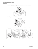
2.
Lift up the tray module to be installed at the top level by holding the parts as shown in the
diagram.
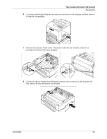
3.
Align the front and back corners of the top and bottom tray modules, and slowly lower the
top module so that the guide pins at the 4 corners of the bottom module fit into the holes at
the base plate of the top module.
NOTE:
The tray module must be lowered gently. Otherwise, the interior parts may be damaged.
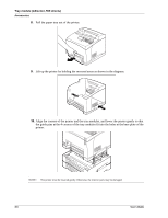
4.
Insert the fasteners provided into the 2 locations inside of the tray module and 2 locations
at the back of the tray module. Insert the fasteners securely.