Sony HVR1500A Product Manual (HVE-1500A Operating Manuals) - Page 10
Option Boards, Video process control
 |
View all Sony HVR1500A manuals
Add to My Manuals
Save this manual to your list of manuals |
Page 10 highlights
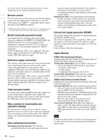
Chapter 1 Overview In a relay vehicle, the unit can also be used as a viewer supporting various analog and digital formats. Remote control The unit can be operated by remote control from an editing control unit that supports the i.LINK inferface, the RS422A interface or a SIRCS 1) -compatible remote control unit such as the DSRM-10 (option). 1) SIRCS (Sony Integrated Remote Control System): A command protocol to remote control Sony professional videocassette recorders/players. Built-in timecode generator/reader An internal timecode generator and reader enables timecode compliant with SMPTE (for 1080/60i)/EBU (for 1080/50i) format to be recorded and played back. Outputting or inputting timecode (LTC) to or from an external device is also possible using the TC IN/OUT connectors. For DVCAM format, VITC is also supported. This unit further supports embedded TC for SD-SDI input and output or HD-SDI input and output. Reference signal connection The reference video input connector of the unit is provided with a loop-through connector which can be used to connect the input reference video signal to other equipment. When there is no loop-through connection, the reference video input connector is automatically provided with a 75 Ω termination. This unit supports input of SD reference signals and HD reference signals (1080i tri-level sync signals). A loopthrough output connector is provided for reference signal input so that the input SD or HD sync signals can be through output. Video process control For analog video output and SDI-format video output, you can use menu items to adjust the video output level, chroma signal output level, setup level and chroma phase. The HD output can be adjusted independently. Menu system for functionality and operation settings The unit provides a menu system to make its various functions easier to use and set up its operation conditions. Also, by assigning a desired menu item to the ASSIGN button, you can recall frequently used functions more rapidly. Easy maintenance functions Self-diagnostic/alarm function: This function automatically detects setup and connection errors, operation faults, and other problems. It also displays a description of the problem, its cause, and the recommended response on the monitor screen or time counter display. Digital hours meter: The digital hours meter functions include four kinds of tally operations for operating hours, head drum usage hours, tape transport hours, and tape threading/unthreading times. The tally results can be displayed on the monitor screen or the time counter display. Internal test signal generator (SD/HD) The unit has built-in video and audio test signal generators for both SD and HD formats. The video test signal generator can produce either a color bar signal or a black burst signal. The audio test signal generator can generate either a silent signal or a 1-kHz sine wave signal. Carry out these selections in the menus. Option Boards HVBK-1505 Analog Input Board Installing this in the unit enables the following formats of analog video/audio signals to be input. Analog video signal input: The three BNC connectors are each used to input the following three signal types. • Composite video signal • S-video signal • Component video signal (Y, R-Y, B-Y) Analog audio signal input: XLR connector (female) You can input two channels of analog audio signals. HVBK-1520 Format Converter Board Installation of this board extends the functions of this unit in the following ways. Upconvert function: SD video signals played back on this unit can be upconverted and output as HD-SDI video signals (SMPTE 292M compliant). HD-SDI output signals have embedded timecode and embedded audio (four channels) synchronized to the upconverted video signals. SD video signal input to this unit can also be upconverted and output as HD-SDI signals. Cross-convert function: When HD video signals are input, or when SD video signals are upconverted, or when HDV recorded tapes are played back, the HDSDI output signal format can be converted to 1080i or 720p. Note Consult your Sony dealer or a Sony service representative for more information about purchasing and installing an option board. 10 Features
-
 1
1 -
2
-
3
-
4
-
 5
5 -
 6
6 -
 7
7 -
 8
8 -
 9
9 -
 10
10 -
 11
11 -
 12
12 -
 13
13 -
 14
14 -
 15
15 -
16
-
17
-
18
-
19
-
20
-
21
-
22
-
23
-
24
-
25
-
26
-
27
-
28
-
29
-
30
-
31
-
32
-
33
-
34
-
35
-
36
-
37
-
38
-
39
-
40
-
41
-
42
-
43
-
44
-
45
-
46
-
47
-
48
-
49
-
50
-
51
-
52
-
53
-
54
-
55
-
56
-
57
-
58
-
59
-
60
-
61
-
62
-
63
-
64
-
65
-
66
-
67
-
68
-
69
-
70
-
71
-
72
-
73
-
74
-
75
-
76
-
77
-
78
-
79
-
80
-
81
-
82
-
83
-
84
-
85
-
86
-
87
-
88
-
89
-
90
-
91
-
92
-
93
-
94
-
95
-
96
-
97
-
98
-
99
-
100
-
101
-
102
-
103
-
104
-
105
-
106
-
107
-
108
-
109
-
110
-
111
 |
 |
