Sony HVR1500A Product Manual (HVE-1500A Operating Manuals) - Page 19
Remote control switch/indicator Arrow buttons, Superimposed text information
 |
View all Sony HVR1500A manuals
Add to My Manuals
Save this manual to your list of manuals |
Page 19 highlights
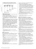
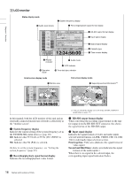
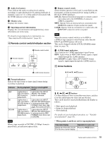
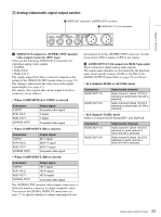
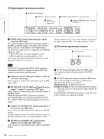
Chapter 1 Overview m Audio level meters These indicate the audio recording levels (during recording) or audio playback levels (during playback) of channels 1 and 2 or 1 to 4. If the audio level exceeds 0 dB, the OVER indicator at the top lights. n Monitor area Displays the monitor video. o Superimposed text information Displays the text information and supplementary status information set in the menu. For details of superimposed text information, see "Superimposed Text Information" (page 29). 4 Remote control switch/indicator section 1 Format indicators 2 Remote control switch LOCAL 9PIN i.LINK b Remote control switch Select whether operation of this unit is controlled from the front panel, or from an external device (using i.LINK or RS-422A (9PIN) interface). LOCAL: Operate from the front panel or a remote control unit connected to the CONTROL-S connector (SIRCS-compatible). 9PIN: Operate from an external device connected to the REMOTE connector (9-pin) on the rear panel. i.LINK: Operate from an external device connected to the HDV/DV connector on the rear panel. Note When the remote control switch is set to 9PIN or i.LINK,no tape transport control buttons other than the EJECT and STOP buttons will work. This can be changed with the LOCAL ENABLE menu item (see page 76). c i.LINK format indicators These indicate the i.LINK input/output signal format. HDV: Lights when an HDV 1080i format signal is input/ output through the i.LINK interface. DVCAM (DV): Lights when a DVCAM/DV format signal is input/output through the i.LINK interface. HDV DVCAM (DV) 5 Arrow buttons 3 i.LINK format indicators M, m,
-
 1
1 -
2
-
3
-
4
-
5
-
6
-
7
-
8
-
9
-
10
-
11
-
12
-
13
-
 14
14 -
 15
15 -
 16
16 -
 17
17 -
 18
18 -
 19
19 -
 20
20 -
 21
21 -
 22
22 -
 23
23 -
 24
24 -
25
-
26
-
27
-
28
-
29
-
30
-
31
-
32
-
33
-
34
-
35
-
36
-
37
-
38
-
39
-
40
-
41
-
42
-
43
-
44
-
45
-
46
-
47
-
48
-
49
-
50
-
51
-
52
-
53
-
54
-
55
-
56
-
57
-
58
-
59
-
60
-
61
-
62
-
63
-
64
-
65
-
66
-
67
-
68
-
69
-
70
-
71
-
72
-
73
-
74
-
75
-
76
-
77
-
78
-
79
-
80
-
81
-
82
-
83
-
84
-
85
-
86
-
87
-
88
-
89
-
90
-
91
-
92
-
93
-
94
-
95
-
96
-
97
-
98
-
99
-
100
-
101
-
102
-
103
-
104
-
105
-
106
-
107
-
108
-
109
-
110
-
111
 |
 |
