Sony HVR1500A Product Manual (HVE-1500A Operating Manuals) - Page 22
Analog video/audio signal input optional HVBK-1505 board required, When S VIDEO is selected
 |
View all Sony HVR1500A manuals
Add to My Manuals
Save this manual to your list of manuals |
Page 22 highlights
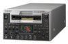
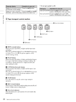
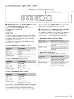
Chapter 1 Overview Note When i.LINK input is selected, the playback output signal does not synchronize to the reference video signal input. 1 Analog video/audio signal input section (optional HVBK-1505 board required) The connectors in this section are available when the optional HVBK-1505 board is installed. 1 VIDEO IN connectors 2 AUDIO IN 1/3, 2/4 connectors VIDEO IN Y/S-Y/CPST R-Y/S-C B-Y AUDIO IN 1/3 2/4 a VIDEO IN connectors (BNC type) There are the following VIDEO IN connectors for inputting analog video signals: • Y/S-Y/CPST (loop-through connectors) • R-Y/S-C • B-Y The signals input to these connectors depend on the selection made with the SD VIDEO button (see page 14) in the video/audio input selection section. The selection is indicated in the video area of the input signal display (see page 16). The analog video signals that can be input to these connectors are as follows. • When COMPOSITE is selected Connectors Y/S-Y/CPST R-Y/S-C B-Y Input signal Composite video signal not usable not usable The two Y/S-Y/CPST connectors are loop-through connectors. When using the signal input to the left connector as a composite video signal, for example, you can bridge-connect the signal to other equipment via the right connector (marked ). When no connection is made to the right connector, the left connector is terminated with an impedance of 75 Ω automatically. • When S VIDEO is selected Connectors Y/S-Y/CPST R-Y/S-C B-Y Input signal Y signal C signal (3.58 MHz) not usable • When Y-R, B is selected Connectors Y/S-Y/CPST R-Y/S-C B-Y Input signal Y signal R-Y signal B-Y signal b AUDIO IN 1/3, 2/4 connectors (XLR 3-pin, female) Use these connectors to input analog audio signals from an external video cassette player or other audio equipment. The signals input to these connectors are recorded on the audio channels determined by the current audio recording mode, as follows. • When in 2-channel (48 kHz) mode Connectors AUDIO IN 1/3 AUDIO IN 2/4 Audio channels on which input signals are recorded Audio channel 1 Audio channel 2 • When in 4-channel (32 kHz) mode Connectors AUDIO IN 1/3 AUDIO IN 2/4 Audio channels on which input signals are recorded Audio channels 1 and 3 Audio channels 2 and 4 You can switch the audio recording mode with the REC MODE menu item (see page 83). However, HDV recording is always 2-channel mode, regardless of the menu item setting. 22 Names and Functions of Parts
-
 1
1 -
2
-
3
-
4
-
5
-
6
-
7
-
8
-
9
-
10
-
11
-
12
-
13
-
14
-
15
-
16
-
 17
17 -
 18
18 -
 19
19 -
 20
20 -
 21
21 -
 22
22 -
 23
23 -
 24
24 -
 25
25 -
 26
26 -
 27
27 -
28
-
29
-
30
-
31
-
32
-
33
-
34
-
35
-
36
-
37
-
38
-
39
-
40
-
41
-
42
-
43
-
44
-
45
-
46
-
47
-
48
-
49
-
50
-
51
-
52
-
53
-
54
-
55
-
56
-
57
-
58
-
59
-
60
-
61
-
62
-
63
-
64
-
65
-
66
-
67
-
68
-
69
-
70
-
71
-
72
-
73
-
74
-
75
-
76
-
77
-
78
-
79
-
80
-
81
-
82
-
83
-
84
-
85
-
86
-
87
-
88
-
89
-
90
-
91
-
92
-
93
-
94
-
95
-
96
-
97
-
98
-
99
-
100
-
101
-
102
-
103
-
104
-
105
-
106
-
107
-
108
-
109
-
110
-
111
 |
 |
