Sony HVR1500A Product Manual (HVE-1500A Operating Manuals) - Page 18
When COMPONENT SD is selected
 |
View all Sony HVR1500A manuals
Add to My Manuals
Save this manual to your list of manuals |
Page 18 highlights
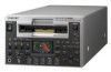
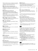
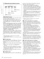
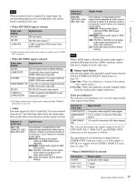
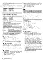
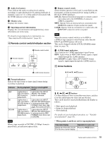
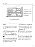
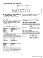
Chapter 1 Overview Connectors Output signal (SUPER) CPST Composite video signal • When COMPONENT SD is selected Connectors Output signal Y/CPST SD Y signal Pr/R-Y/S-C SD R-Y signal Pb/B-Y/S-Y SD B-Y signal (SUPER) CPST Composite video signal • When COMPONENT HD is selected Connectors Output signal Y/CPST HD Y signal Pr/R-Y/S-C HD Pr signal Pb/B-Y/S-Y HD Pb signal (SUPER) CPST Composite video signal Audio area indicators Indicates the channel selection for audio signal output from the AUDIO OUT 1/3 and AUDIO OUT 2/4 connectors on the rear panel. Indicators CH 1/2 CH 3/4 Functions Channel 1 is output from the AUDIO OUT 1/ 3 connector, and channel 2 from the AUDIO OUT 2/4 connector. Channel 3 is output from the AUDIO OUT 1/ 3 connector, and channel 4 from the AUDIO OUT 2/4 connector. You can change the output channel selection with the AUDIO OUTPUT menu item (see page 85). f Cassette type Indicates the type of the loaded cassette. : Lights when a cassette is loaded. : Lights when a cassette provided with a memory chip ("cassette memory") is loaded. CL : Lights when a cassette is loaded on which ClipLink log data is stored in the cassette memory. g Time counter display Indicates the count value of the time counter, timecode, VITC, or user bit data depending on the settings of the COUNTER SELECT button and the TC SELECT menu item (see page 80). Also used to display error messages, edit data, setup menu data, etc. h Audio mode • During playback, this indicates the playback audio mode in which the tape being played back was recorded. 48K: 2-channel mode (48 kHz) 44.1K: 2-channel mode (44.1 kHz) 32K: 4-channel mode (32 kHz) • During recording or when in E-E mode, this indicates the setting of the audio recording mode set with the REC MODE menu item (see page 83). 48K: 2-channel mode (48 kHz) 32K: 4-channel mode (32 kHz) Note In recording of i.LINK (HDV) input, 1080/60i or 1080/50i format 4-channel mode audio is recorded without change. However, only up to 2 audio channels can be played back on this unit. i VITC indicator Lights when VITC is being read or recorded regardless of time data shown in the time counter display. j Time data type indicator Indicates the type of time data currently shown in the time counter display. TC: SMPTE timecode UB: User bit data CNT: Count value of the time counter VITC: VITC timecode VIUB: VITC user bit data k Repeat (repeat playback) indicator Lights when the REPEAT MODE menu item (see page 75) is set to ON to enable the repeat playback function. l Operation mode This indicates the current operating modes. REC INHI (recording inhibit mode): Lights when the REC/SAVE switch on the loaded cassette is in the SAVE position (recording inhibited) or when the REC INHIBIT menu item is set to ON. NO EDIT (not editable): Lights during playback of a tape that contains a recording in other than DVCAM format. When this indicator is lit, the recordings contained in the tape can be used as source material for editing, but editing operations such as insert editing and assemble editing cannot be performed on such tape. This indicator also lights during editing operation when the audio recording mode selected on this unit does not coincide with that of the loaded tape. EDIT MODE: Lights when this unit is set in editing mode such as assemble editing or insert editing under the control of either an editing control unit connected to the REMOTE connector or device connected to the HDV/DV connector on the rear panel (see page 21). This unit can be put into editing mode only when the recording format is set to DVCAM. 18 Names and Functions of Parts
-
 1
1 -
2
-
3
-
4
-
5
-
6
-
7
-
8
-
9
-
10
-
11
-
12
-
 13
13 -
 14
14 -
 15
15 -
 16
16 -
 17
17 -
 18
18 -
 19
19 -
 20
20 -
 21
21 -
 22
22 -
 23
23 -
24
-
25
-
26
-
27
-
28
-
29
-
30
-
31
-
32
-
33
-
34
-
35
-
36
-
37
-
38
-
39
-
40
-
41
-
42
-
43
-
44
-
45
-
46
-
47
-
48
-
49
-
50
-
51
-
52
-
53
-
54
-
55
-
56
-
57
-
58
-
59
-
60
-
61
-
62
-
63
-
64
-
65
-
66
-
67
-
68
-
69
-
70
-
71
-
72
-
73
-
74
-
75
-
76
-
77
-
78
-
79
-
80
-
81
-
82
-
83
-
84
-
85
-
86
-
87
-
88
-
89
-
90
-
91
-
92
-
93
-
94
-
95
-
96
-
97
-
98
-
99
-
100
-
101
-
102
-
103
-
104
-
105
-
106
-
107
-
108
-
109
-
110
-
111
 |
 |
