Sony HVR1500A Product Manual (HVE-1500A Operating Manuals) - Page 14
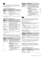
Video/audio input selection INPUT SELECT buttons
 |
View all Sony HVR1500A manuals
Add to My Manuals
Save this manual to your list of manuals |
Page 14 highlights
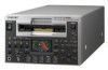
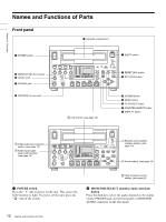
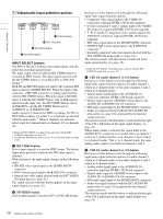
Chapter 1 Overview A Video/audio input selection section INPUT SELECT HD VIDEO SD VIDEO CH1 1/2 CH2 3/4 d CH2 3/4 button c CH1 1/2 button 2 SD VIDEO button 1 HD VIDEO button INPUT SELECT buttons The INPUT SELECT buttons select input signals, and also select the recording signal format. The input signal selected with the HD VIDEO button is recorded in HDV format. The input signal selected with the SD VIDEO button is recorded in DV or DVCAM format. 1) Both SD and HD SDI signals are input to the common SDI input connector (SD/HD SDI IN). When the input to this connector is HD-SDI, select the recording signal format with the HD VIDEO button. When the input is SD-SDI, select it with the SD VIDEO button. The i.LINK input is selected in the same way: the HD VIDEO button selects i.LINK:HDV, and the SD VIDEO button selects i.LINK:DV or i.LINK:DVCAM. Audio signal is 2 channels for HDV recording. For DV or DVCAM recording, it is either 2 or 4 channels, as selected with the setup menu. 2) When 4 channels are selected, select input in 2-channel units as channels 1/2 or channels 3/4. 1) Make the DVCAM/DV recording format selection with the REC FORMAT menu item (see page 76). 2) Use the REC MODE menu item (see page 83) to select the audio recording mode. a HD VIDEO button Selects input signals to record in HDV format. The button lights when pressed to indicate that HD video input is selected. With each press, the input signal changes in the following order. • HD-SDI video signal input to the SD/HD SDI IN connector • HDV format signal input to the HDV/DV connector • Internal test video signal selected with the INT VIDEO SG menu item (see page 81) The signal selected with this button appears in the input signal display (see page 16). b SD VIDEO button Selects input signals to record in DV or DVCAM format. Each press of this button cycles through the following input video signal selection options. • Composite video signal input to the VIDEO IN connectors (optional HVBK-1505 board required) • S-video (separated Y and C) signals input to the VIDEO IN connectors (optional HVBK-1505 board required) • Y, R-Y and B-Y component video signals input to the VIDEO IN connectors (optional HVBK-1505 board required) • SDI video signal input to the SD/HD SDI IN connector • DV/DVCAM format signal input to the HDV/DV connector 1) • Internally generated video test signal (selected with the INT VIDEO SG menu item (see page 81)) The selection made with this button is indicated in the input signal display (see page 16). 1) Make the DVCAM/DV recording format selection with the REC FORMAT menu item (see page 76). c CH1 1/2 (audio channel 1 or 1/2) button Each press of this button cycles through the following input audio signal selection options for audio channel 1 (when in 2-channel mode) or for audio channels 1 and 2 (when in 4-channel mode). • Analog audio signal input to the AUDIO IN 1/3 connector (optional HVBK-1505 board required) • Digital audio signal in AES/EBU format input to the AUDIO I/O (AES/EBU) IN 1/2 connector • SDI audio signal input to the SD/HD SDI IN connector • Audio test signal (selected with the INT AUDIO SG menu item (see page 84)) generated by the internal signal generator The selection made with this button is indicated to the right of the CH-1 indication in the input signal display (see page 16). When analog audio is selected, the signal input to the AUDIO IN 1/3 connector is recorded either on channel 1 (when in 2- channel mode) or on channels 1 and 3 (when in 4-channel mode). That is, in 4-channel mode, the same analog audio signal is recorded on channels 1 and 3. d CH2 3/4 (audio channel 2 or 3/4) button Each press of this button cycles through the following input audio signal selection options for audio channel 2 (when in 2-channel mode) or for audio channels 3 and 4 (when in 4-channel mode). • Analog audio signal input to the AUDIO IN 2/4 connector (optional HVBK-1505 board required) • Digital audio signal in AES/EBU format input to the AUDIO I/O (AES/EBU) IN 3/4 connector • SDI audio signal input to the SD/HD SDI IN connector • Audio test signal (selected with the INT AUDIO SG menu item (see page 84)) generated by the internal signal generator The selection made with this button is indicated to the right of the CH-2 indication in the input signal display (see page 16). 14 Names and Functions of Parts
-
 1
1 -
2
-
3
-
4
-
5
-
6
-
7
-
8
-
 9
9 -
 10
10 -
 11
11 -
 12
12 -
 13
13 -
 14
14 -
 15
15 -
 16
16 -
 17
17 -
 18
18 -
 19
19 -
20
-
21
-
22
-
23
-
24
-
25
-
26
-
27
-
28
-
29
-
30
-
31
-
32
-
33
-
34
-
35
-
36
-
37
-
38
-
39
-
40
-
41
-
42
-
43
-
44
-
45
-
46
-
47
-
48
-
49
-
50
-
51
-
52
-
53
-
54
-
55
-
56
-
57
-
58
-
59
-
60
-
61
-
62
-
63
-
64
-
65
-
66
-
67
-
68
-
69
-
70
-
71
-
72
-
73
-
74
-
75
-
76
-
77
-
78
-
79
-
80
-
81
-
82
-
83
-
84
-
85
-
86
-
87
-
88
-
89
-
90
-
91
-
92
-
93
-
94
-
95
-
96
-
97
-
98
-
99
-
100
-
101
-
102
-
103
-
104
-
105
-
106
-
107
-
108
-
109
-
110
-
111
 |
 |
