Sony HVR1500A Product Manual (HVE-1500A Operating Manuals) - Page 24
Digital signal input/output Timecode input/output
 |
View all Sony HVR1500A manuals
Add to My Manuals
Save this manual to your list of manuals |
Page 24 highlights
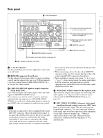
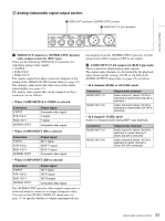
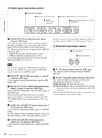
Chapter 1 Overview 3 Digital signal input/output section 1 SD/HD SDI IN connector 2 SDI OUT1, OUT2 connectors 3 HD SDI OUT1, OUT2 connectors 4 AUDIO I/O (AES/EBU) IN 1/2, 3/4 connectors 5 AUDIO I/O (AES/EBU) OUT 1/2, 3/4 connectors IN(SD/HD) SDI OUT1 OUT2 SDI OUT1 OUT2 HD SDI IN AUDIO I/O (AES/EBU) OUT 1/2 3/4 1/2 3/4 a SD/HD SDI IN (Serial Digital Interface input) connector (BNC type) This connector inputs digital video and audio signals in HD-SDI or SD-SDI format. Select HD or SD with the INPUT SELECT HD VIDEO or SD VIDEO button. The following signal formats are supported when HD-SDI signals are input. • 1080/59.94i (when the system frequency is 60i) • 1080/50i (when the system frequency is 50i) The current input signal selections are indicated in the input signal display (see page 16). Note The 1035/59.94i signal and 1080/29.97PsF signal are treated as the 1080/59.94i signal, and the 1080/25PsF signal is treated as the 1080/50i signal. b SDI OUT1, OUT2 (SDI signal output 1, output 2) connectors (BNC type) These connectors output video and audio signals in SDI format (SD). c HD SDI OUT1, OUT2 (HD Serial Digital Interface output 1, output 2) connectors (BNC type) These connectors output digital video and audio signals in HD-SDI format. When the optional HVBK-1520 board is installed, upconverted signals are output during playback of DV/ DVCAM/DVCPRO tapes and during input of SD video signals. d AUDIO I/O (AES/EBU) IN (digital audio input) 1/ 2, 3/4 connectors (BNC type) These connectors input digital audio signals in AES/EBU format. The left connector (1/2) is for audio channels 1 and 2, and the right connector (3/4) is for audio channels 3 and 4. e AUDIO I/O (AES/EBU) OUT (digital audio output) 1/2, 3/4 connectors (BNC type) These connectors output digital audio signals in AES/EBU format. The left connector (1/2) is for audio channels 1 and 2, and the right connector (3/4) is for audio channels 3 and 4. D Timecode input/output section 1 TC IN connector TC IN 2 TC OUT connector OUT a TC IN (timecode input) connector (BNC type) This connector inputs externally generated SMPTE timecode. b TC OUT (timecode output) connector (BNC type) This connector outputs a timecode according to the operating state of the unit, as follows. During playback: the playback timecode During recording: the timecode generated by the internal timecode generator or the timecode input to the TC IN connector. When the EE OUT PHASE menu item (see page 80) is set to NO OUTPUT, no timecode is output. 24 Names and Functions of Parts
-
 1
1 -
2
-
3
-
4
-
5
-
6
-
7
-
8
-
9
-
10
-
11
-
12
-
13
-
14
-
15
-
16
-
17
-
18
-
 19
19 -
 20
20 -
 21
21 -
 22
22 -
 23
23 -
 24
24 -
 25
25 -
 26
26 -
 27
27 -
 28
28 -
 29
29 -
30
-
31
-
32
-
33
-
34
-
35
-
36
-
37
-
38
-
39
-
40
-
41
-
42
-
43
-
44
-
45
-
46
-
47
-
48
-
49
-
50
-
51
-
52
-
53
-
54
-
55
-
56
-
57
-
58
-
59
-
60
-
61
-
62
-
63
-
64
-
65
-
66
-
67
-
68
-
69
-
70
-
71
-
72
-
73
-
74
-
75
-
76
-
77
-
78
-
79
-
80
-
81
-
82
-
83
-
84
-
85
-
86
-
87
-
88
-
89
-
90
-
91
-
92
-
93
-
94
-
95
-
96
-
97
-
98
-
99
-
100
-
101
-
102
-
103
-
104
-
105
-
106
-
107
-
108
-
109
-
110
-
111
 |
 |
