Sony HVR1500A Product Manual (HVE-1500A Operating Manuals) - Page 12
Names and Functions of Parts, Front panel
 |
View all Sony HVR1500A manuals
Add to My Manuals
Save this manual to your list of manuals |
Page 12 highlights
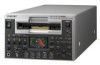
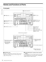
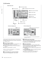
Chapter 1 Overview Names and Functions of Parts Front panel 6 Cassette compartment 1 POWER switch 2 MONITOR SELECT button 3 LEVEL knob 4 PHONES jack POWER EJECT INPUT SELECT HD VIDEO SD VIDEO CH1 1/2 CH2 3/4 REC/PB LEVEL 1 2 3 4 LEVEL PHONES VARIABLE REC PRESET PB CONTROL-S MONITOR SELECT REW OVER OVER 0 60i 720 30p 720 60p -12 -20 -30 -40 -60 CH1 CH2 EDIT MODE REPEAT TC VITC 48K 01:23:45:15 DISPLAY COUNTER SELECT PLAY F FWD STOP REC LOCAL 9PIN i.LINK MENU HDV DVCAM (DV) ASSIGN RESET(NO) TC PRESET SET(YES) A B 7 EJECT button 8 RESET (NO) button 9 SET (YES) button 5 CONTROL-S connector 3 LCD monitor (see page 16) q; ASSIGN button qa MENU button qs TC PRESET button qd COUNTER SELECT button n DISPLAY button 1 Video/audio input selection section (see page 14) 2 Audio input/output level control section (see page 15) POWER EJECT INPUT SELECT HD VIDEO SD VIDEO CH1 1/2 CH2 3/4 REC/PB LEVEL 1 2 3 4 LEVEL PHONES VARIABLE REC PRESET PB CONTROL-S MONITOR SELECT REW OVER OVER 0 60i 720 30p 720 60p -12 -20 -30 -40 -60 CH1 CH2 EDIT MODE REPEAT TC VITC 48K 01:23:45:15 DISPLAY COUNTER SELECT PLAY F FWD STOP REC LOCAL 9PIN i.LINK MENU HDV DVCAM (DV) ASSIGN RESET(NO) TC PRESET SET(YES) A B 4 Remote control switch/ indicator section (see page 19) 5 Arrow buttons (see page 19) a POWER switch Press the " " side to power on the unit. This causes the LCD monitor to light. To power off the unit, press the " " side of the switch. F Tape transport control section (see page 20) b MONITOR SELECT (monitor audio selection) button Press this button to select the audio channels to be output via the PHONES jack on the front panel or MONITOR AUDIO connector on the rear panel. 12 Names and Functions of Parts
-
 1
1 -
2
-
3
-
4
-
5
-
6
-
 7
7 -
 8
8 -
 9
9 -
 10
10 -
 11
11 -
 12
12 -
 13
13 -
 14
14 -
 15
15 -
 16
16 -
 17
17 -
18
-
19
-
20
-
21
-
22
-
23
-
24
-
25
-
26
-
27
-
28
-
29
-
30
-
31
-
32
-
33
-
34
-
35
-
36
-
37
-
38
-
39
-
40
-
41
-
42
-
43
-
44
-
45
-
46
-
47
-
48
-
49
-
50
-
51
-
52
-
53
-
54
-
55
-
56
-
57
-
58
-
59
-
60
-
61
-
62
-
63
-
64
-
65
-
66
-
67
-
68
-
69
-
70
-
71
-
72
-
73
-
74
-
75
-
76
-
77
-
78
-
79
-
80
-
81
-
82
-
83
-
84
-
85
-
86
-
87
-
88
-
89
-
90
-
91
-
92
-
93
-
94
-
95
-
96
-
97
-
98
-
99
-
100
-
101
-
102
-
103
-
104
-
105
-
106
-
107
-
108
-
109
-
110
-
111
 |
 |
