Sony HVR1500A Product Manual (HVE-1500A Operating Manuals) - Page 16
CLCD monitor
 |
View all Sony HVR1500A manuals
Add to My Manuals
Save this manual to your list of manuals |
Page 16 highlights
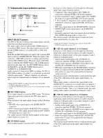
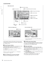
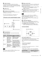
Chapter 1 Overview C LCD monitor Status display mode qd Audio level meters 1 System frequency display 2 Recording/playback signal format display OVER OVER 0 -12 -20 -30 -40 -60 CH1 CH2 EDIT MODE REPEAT 60i INPUT 720 30p 720 60p COMPOSITE CH-1 CH-2 AES/EBU ANALOG OUTPUT COMPONENT SD CH-1 / 2 TC VITC 48K 12:34:56:00 3 HD-SDI output format display 4 Input signal display 5 Output signal display 6 Cassette type 7 Time counter display qa Repeat indicator 8 Audio mode 9 VITC indicator qs Operation mode 0 Time data type indicator Small screen display mode n Monitor area OVER OVER 0 -12 -20 -30 -40 -60 12 34 TC VITC 48K 12:34:56:00 Full screen display mode qg Superimposed text information a) TCR 12 : 34 : 56 : 00 PLAY LOCK IP FV In this manual, both the LCD monitor of this unit and an externally connected monitor are referred to collectively as the "monitor screen". a System frequency display Indicates the current setting of the system frequency set in the SYSTEM SEL menu item (see page 86). 60i: Indicates that 59.94i (J) or 59.94i (UC) (NTSC) is selected. 50i: Indicates that 50i (PAL) is selected. On how to set the system frequency, see "Setting the system frequency" (page 25). b Recording/playback signal format display Indicates the recording/playback video format. a) You can switch the display on or off in the CHARA. DISPLAY menu item (see page 77). c HD-SDI output format display When converting the recording signal format on the tape for output from the HD SDI OUT connector, this shows the signal format of the HD-SDI output. d Input signal display Indicates the signal formats of video and audio inputs selected with the buttons (i.LINK, VIDEO, CH1 1/2, CH2 3/4) in video/audio input selection section. First (top) line: Video area (Indicates the signal format of video input.) Second and third lines: Audio area (Indicates the signal formats of the audio inputs.) When there is no signal in the selected input, the corresponding input signal indication flashes. 16 Names and Functions of Parts
-
 1
1 -
2
-
3
-
4
-
5
-
6
-
7
-
8
-
9
-
10
-
 11
11 -
 12
12 -
 13
13 -
 14
14 -
 15
15 -
 16
16 -
 17
17 -
 18
18 -
 19
19 -
 20
20 -
 21
21 -
22
-
23
-
24
-
25
-
26
-
27
-
28
-
29
-
30
-
31
-
32
-
33
-
34
-
35
-
36
-
37
-
38
-
39
-
40
-
41
-
42
-
43
-
44
-
45
-
46
-
47
-
48
-
49
-
50
-
51
-
52
-
53
-
54
-
55
-
56
-
57
-
58
-
59
-
60
-
61
-
62
-
63
-
64
-
65
-
66
-
67
-
68
-
69
-
70
-
71
-
72
-
73
-
74
-
75
-
76
-
77
-
78
-
79
-
80
-
81
-
82
-
83
-
84
-
85
-
86
-
87
-
88
-
89
-
90
-
91
-
92
-
93
-
94
-
95
-
96
-
97
-
98
-
99
-
100
-
101
-
102
-
103
-
104
-
105
-
106
-
107
-
108
-
109
-
110
-
111
 |
 |
