Sony HVR1500A Product Manual (HVE-1500A Operating Manuals) - Page 59
VIDEO OUT, SUPER CPST, MONITOR, AUDIO, i.LINK, SUPER, HDV/DV, DSR-2000A/2000AP, recorder settings
 |
View all Sony HVR1500A manuals
Add to My Manuals
Save this manual to your list of manuals |
Page 59 highlights
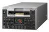
1 75 Ω coaxial cable (not supplied) 2 Pin plug cable (not supplied) 3 i.LINK cable (not supplied) SD monitor the same. If the audio modes are different, an alarm is displayed to tell that editing is impossible. DSR-2000A/2000AP (recorder) settings Settings on this unit INPUT SELECT menu item: Remote control switch: i.LINK i.LINK Remote control setting section: HD VIDEO button lit For details of DSR-2000A/2000AP settings, refer to the DSR-2000A/2000AP Operating Instructions. Audio input 1 Composite video input MONITOR AUDIO 2 VIDEO OUT (SUPER) CPST VIDEO IN Y/S-Y/CPST R-Y/S-C B-Y AC IN AUDIO IN 1/3 2/4 REF.VIDEO IN(SD/HD) VIDEO OUT (SUPER) AUDIO Y/CPST Pr/R-Y/S-C Pb/B-Y/S-Y CPST OUT IN(SD/HD) SDI OUT1 OUT2 SDI OUT1 OUT2 HD SDI 1/3 2/4 IN AUDIO I/O (AES/EBU) OUT TC IN OUT MONITOR AUDIO 1/2 3/4 1/2 3/4 HDV/DV REMOTE HVR-1500A (this unit as player) HDV/DV DSR-2000A/2000AP (recorder) 3 i.LINK VIDEO OUT 3 1 MONITOR (SUPER) AUDIO Composite video input 2 Audio input Chapter 5 Connections and Settings for Editing SD monitor Note For audio editing, make sure that the audio recording mode of the source tape and that of the DSR-2000A/2000AP are 59 Connection Using i.LINK
-
 1
1 -
2
-
3
-
4
-
5
-
6
-
7
-
8
-
9
-
10
-
11
-
12
-
13
-
14
-
15
-
16
-
17
-
18
-
19
-
20
-
21
-
22
-
23
-
24
-
25
-
26
-
27
-
28
-
29
-
30
-
31
-
32
-
33
-
34
-
35
-
36
-
37
-
38
-
39
-
40
-
41
-
42
-
43
-
44
-
45
-
46
-
47
-
48
-
49
-
50
-
51
-
52
-
53
-
 54
54 -
 55
55 -
 56
56 -
 57
57 -
 58
58 -
 59
59 -
 60
60 -
 61
61 -
 62
62 -
 63
63 -
 64
64 -
65
-
66
-
67
-
68
-
69
-
70
-
71
-
72
-
73
-
74
-
75
-
76
-
77
-
78
-
79
-
80
-
81
-
82
-
83
-
84
-
85
-
86
-
87
-
88
-
89
-
90
-
91
-
92
-
93
-
94
-
95
-
96
-
97
-
98
-
99
-
100
-
101
-
102
-
103
-
104
-
105
-
106
-
107
-
108
-
109
-
110
-
111
 |
 |
