Sony HVR1500A Product Manual (HVE-1500A Operating Manuals) - Page 79
REC RUN [>> REC RUN], ON DF [>> ON DF]
 |
View all Sony HVR1500A manuals
Add to My Manuals
Save this manual to your list of manuals |
Page 79 highlights
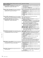
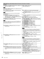
DISPLAY CONTROL [Display]: Settings related to monitor Description of settings display and indicators OVER DISP HOLD [> Hold OVER]: Determine whether or not to hold the OVER indicator on the audio level meters once the indicator lights. *OFF [>> OFF]: Do not hold the OVER indicator. ON (HOLD) [>> ON]: Hold the OVER indicator. Note With ON selected, once the indicator is held it will remain held unless you change the setting to OFF. LCD [> LCD]: Adjust LCD monitor display quality. BACK LIGHT [>> BK Light]: 1 [>>> 1] to 12 [>>> 12]: Larger numerical values indicate Set backlight brightness. higher brightness Factory default setting: *6 [>>> 6] GAMMA [>> GAMMA]: OFF [>>> OFF]: No adjustment Adjust the slope of the TYPE 1 [>>> Type1]: Set to Type 1. gamma correction curve. *TYPE 2 [>>> Type2]: Set to Type 2. ALARM [> ALARM]: Determine whether alarm messages are OFF [>> OFF]: Alarm messages are not issued. issued or not. *ON [>> ON]: Alarm messages are issued. REF ALARM [> REF ALARM]: Determine whether alarm messages related to the reference video signal are issued or not. OFF [>> OFF]: Alarm messages are not issued. *ON (LIMITED) [>> ON (Limit)]: Alarm messages are issued only during recording mode, E-E mode, REC-pause mode, and EDIT mode. ON [>> ON]: Alarm messages are issued. TIME CODE [Time code]: Settings related to the timecode Description of settings generator TC MODE [> TC mode]: Determine the timecode to use: internal timecode using a preset initial value, regenerated internal timecode (locked to timecode read from tape), or external timecode. *INT PRESET [>> PRESET]: Use internal timecode with a preset initial value. INT REGEN [>> REGEN]: Use internal timecode locked to timecode read from tape. EXT REGEN [>> EXT]: Use external timecode selected as follows. • When TC is selected External timecode input to the TC IN connector. However, if SDI input is selected, in order to support embedded timecode the synchronization priority sequence is as follows. 1 LTC (SD-SDI signal: RP188 or HD-SDI signal: ARIB STD-B4.2.0, and RP188) embedded in the SDI input 2 An Input to the TC IN connector • When VITC is selected The VITC timecode present in the input video signal. 1 When SD-SDI input is selected: The VITC signal superimposed as video signal 2 When HD-SDI input is selected: The VITC signal embedded as ANC DATA. RUN MODE [> RUN mode]: Select the advancement (RUN) mode of the timecode generator. *FREE RUN [>> FREE RUN]: Timecode generator keeps running. REC RUN [>> REC RUN]: Timecode generator runs only while recording. Note Set to FREE RUN when carrying out editing with an editing control unit. With the REC RUN setting, editing will not be carried out correctly. DF MODE [> DF mode]: Select whether the timecode generator and time counter operate in drop frame mode or non-drop frame mode. Normally select drop frame mode to keep in synchronization with real time. The non-drop frame mode is useful for example when using computer graphics, and working on a frame count basis. *ON (DF) [>> ON (DF)]: Drop frame mode OFF (NDF) [>> OFF (NDF)]: Non-drop frame mode Note Displayed only when the system frequency is set to 60i. Chapter 7 Menus 79 Menu Contents
-
 1
1 -
2
-
3
-
4
-
5
-
6
-
7
-
8
-
9
-
10
-
11
-
12
-
13
-
14
-
15
-
16
-
17
-
18
-
19
-
20
-
21
-
22
-
23
-
24
-
25
-
26
-
27
-
28
-
29
-
30
-
31
-
32
-
33
-
34
-
35
-
36
-
37
-
38
-
39
-
40
-
41
-
42
-
43
-
44
-
45
-
46
-
47
-
48
-
49
-
50
-
51
-
52
-
53
-
54
-
55
-
56
-
57
-
58
-
59
-
60
-
61
-
62
-
63
-
64
-
65
-
66
-
67
-
68
-
69
-
70
-
71
-
72
-
73
-
 74
74 -
 75
75 -
 76
76 -
 77
77 -
 78
78 -
 79
79 -
 80
80 -
 81
81 -
 82
82 -
 83
83 -
 84
84 -
85
-
86
-
87
-
88
-
89
-
90
-
91
-
92
-
93
-
94
-
95
-
96
-
97
-
98
-
99
-
100
-
101
-
102
-
103
-
104
-
105
-
106
-
107
-
108
-
109
-
110
-
111
 |
 |
