Dell PowerConnect J-SRX210 Hardware Guide - Page 104
Connecting the Modem to the Console Port on the J-SRX210 Services Gateway
 |
View all Dell PowerConnect J-SRX210 manuals
Add to My Manuals
Save this manual to your list of manuals |
Page 104 highlights
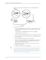
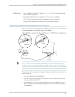
PowerConnect J-SRX210 Services Gateway Hardware Guide An OK response verifies that the modem can communicate successfully with the COM port on the PC or laptop. 6. Configure the modem to answer a call on the first ring, by entering ATS0=1. 7. Configure the modem to accept modem control DTR signals, by entering AT&D1. 8. Disable flow control, by entering AT&K0. 9. Save modem settings, by entering AT&W. Related Topics • Connecting the Modem to the Console Port on the J-SRX210 Services Gateway on page 88 • Connecting to the CLI at the User End for the J-SRX210 Services Gateway on page 89 • J-SRX210 Services Gateway Software Configuration Overview on page 91 Connecting the Modem to the Console Port on the J-SRX210 Services Gateway To connect the dial-up modem to the console port on the services gateway: 1. Turn off power to the services gateway. 2. Turn off power to the modem. 3. Plug one end of the Ethernet cable supplied with your services gateway into the console port (Figure 28 on page 149 shows the console cable connector) on the services gateway. 4. Plug the other end of the Ethernet cable into the RJ-45 to DB-9 serial port adapter supplied with your services gateway. 5. Connect the serial port adapter to a separately purchased DB-9 female to DB-25 male adapter or other adapter appropriate for your modem. 6. Plug the modem adapter into the DB-25 connector on the modem. 7. Connect the modem to your telephone network. 8. Turn on the power to the modem. 9. Power on the services gateway by pressing the Power button on the front panel. Verify that the Power LED on the front panel turns green. NOTE: Most modems have an RS-232 DB-25 connector. You must separately purchase an adapter to connect your modem to the RJ-45 to DB-9 adapter and Ethernet cable supplied with the services gateway. Related Topics • Connecting the Modem at the J-SRX210 Services Gateway End on page 87 • Connecting to the CLI at the User End for the J-SRX210 Services Gateway on page 89 • J-SRX210 Services Gateway Software Configuration Overview on page 91 88
-
 1
1 -
2
-
3
-
4
-
5
-
6
-
7
-
8
-
9
-
10
-
11
-
12
-
13
-
14
-
15
-
16
-
17
-
18
-
19
-
20
-
21
-
22
-
23
-
24
-
25
-
26
-
27
-
28
-
29
-
30
-
31
-
32
-
33
-
34
-
35
-
36
-
37
-
38
-
39
-
40
-
41
-
42
-
43
-
44
-
45
-
46
-
47
-
48
-
49
-
50
-
51
-
52
-
53
-
54
-
55
-
56
-
57
-
58
-
59
-
60
-
61
-
62
-
63
-
64
-
65
-
66
-
67
-
68
-
69
-
70
-
71
-
72
-
73
-
74
-
75
-
76
-
77
-
78
-
79
-
80
-
81
-
82
-
83
-
84
-
85
-
86
-
87
-
88
-
89
-
90
-
91
-
92
-
93
-
94
-
95
-
96
-
97
-
98
-
 99
99 -
 100
100 -
 101
101 -
 102
102 -
 103
103 -
 104
104 -
 105
105 -
 106
106 -
 107
107 -
 108
108 -
 109
109 -
110
-
111
-
112
-
113
-
114
-
115
-
116
-
117
-
118
-
119
-
120
-
121
-
122
-
123
-
124
-
125
-
126
-
127
-
128
-
129
-
130
-
131
-
132
-
133
-
134
-
135
-
136
-
137
-
138
-
139
-
140
-
141
-
142
-
143
-
144
-
145
-
146
-
147
-
148
-
149
-
150
-
151
-
152
-
153
-
154
-
155
-
156
-
157
-
158
-
159
-
160
-
161
-
162
-
163
-
164
-
165
-
166
-
167
-
168
-
169
-
170
-
171
-
172
-
173
-
174
-
175
-
176
-
177
-
178
-
179
-
180
-
181
-
182
 |
 |