Dell PowerConnect J-SRX210 Hardware Guide - Page 63
General Site Guidelines for Installing the J-SRX210 Services Gateway - review
 |
View all Dell PowerConnect J-SRX210 manuals
Add to My Manuals
Save this manual to your list of manuals |
Page 63 highlights
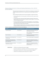
Chapter 7: Preparing the Site for the J-SRX210 Services Gateway Installation Table 19: Site Preparation Checklist for the J-SRX210 Services Gateway Installation (continued) Item or Task Performed Additional Information By Date Notes • Acquire cables and connectors. • Review the maximum distance allowed for each cable. Choose the length of cable based on the distance between the hardware components being connected. • Plan the cable routing and management. "Interface Cable and Wire Specifications for the J-SRX210 Services Gateway" on page 147 Related Topics • J-SRX210 Services Gateway Specifications on page 7 • General Site Guidelines for Installing the J-SRX210 Services Gateway on page 47 • Installation Overview for the J-SRX210 Services Gateway on page 53 • J-SRX210 Services Gateway Cabinet Requirements on page 48 • J-SRX210 Services Gateway Rack Requirements on page 49 • Clearance Requirements for Airflow and Hardware Maintenance of the J-SRX210 Services Gateway on page 50 General Site Guidelines for Installing the J-SRX210 Services Gateway The following precautions help you plan an acceptable operating environment for your J-SRX210 Services Gateway and avoid environmentally caused equipment failures: • For the cooling system to function properly, the airflow around the chassis must be unrestricted. Allow sufficient clearance between the front and back of the chassis and adjacent equipment. Ensure that there is adequate circulation in the installation location. • Follow the ESD procedures to avoid damaging equipment. Static discharge can cause components to fail completely or intermittently over time. • Ensure that the blank Mini-PIM panel is installed in the empty slot to prevent any interruption or reduction in the flow of air across internal components. NOTE: Install the device only in restricted areas, such as dedicated equipment rooms and equipment closets, in accordance with Articles 110-16, 110-17, and 110-18 of the National Electrical Code, ANSI/NFPA 70. Related Topics • J-SRX210 Services Gateway Specifications on page 7 • J-SRX210 Services Gateway Safety Requirements, Warnings, and Guidelines on page 65 • J-SRX210 Services Gateway Cabinet Requirements on page 48 47
-
 1
1 -
2
-
3
-
4
-
5
-
6
-
7
-
8
-
9
-
10
-
11
-
12
-
13
-
14
-
15
-
16
-
17
-
18
-
19
-
20
-
21
-
22
-
23
-
24
-
25
-
26
-
27
-
28
-
29
-
30
-
31
-
32
-
33
-
34
-
35
-
36
-
37
-
38
-
39
-
40
-
41
-
42
-
43
-
44
-
45
-
46
-
47
-
48
-
49
-
50
-
51
-
52
-
53
-
54
-
55
-
56
-
57
-
 58
58 -
 59
59 -
 60
60 -
 61
61 -
 62
62 -
 63
63 -
 64
64 -
 65
65 -
 66
66 -
 67
67 -
 68
68 -
69
-
70
-
71
-
72
-
73
-
74
-
75
-
76
-
77
-
78
-
79
-
80
-
81
-
82
-
83
-
84
-
85
-
86
-
87
-
88
-
89
-
90
-
91
-
92
-
93
-
94
-
95
-
96
-
97
-
98
-
99
-
100
-
101
-
102
-
103
-
104
-
105
-
106
-
107
-
108
-
109
-
110
-
111
-
112
-
113
-
114
-
115
-
116
-
117
-
118
-
119
-
120
-
121
-
122
-
123
-
124
-
125
-
126
-
127
-
128
-
129
-
130
-
131
-
132
-
133
-
134
-
135
-
136
-
137
-
138
-
139
-
140
-
141
-
142
-
143
-
144
-
145
-
146
-
147
-
148
-
149
-
150
-
151
-
152
-
153
-
154
-
155
-
156
-
157
-
158
-
159
-
160
-
161
-
162
-
163
-
164
-
165
-
166
-
167
-
168
-
169
-
170
-
171
-
172
-
173
-
174
-
175
-
176
-
177
-
178
-
179
-
180
-
181
-
182
 |
 |