Dell PowerConnect J-SRX210 Hardware Guide - Page 125
Monitoring the J-SRX210 Services Gateway Components Using LEDs
 |
View all Dell PowerConnect J-SRX210 manuals
Add to My Manuals
Save this manual to your list of manuals |
Page 125 highlights
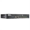
Chapter 18: Monitoring the J-SRX210 Services Gateway Slot State 0 Online 1 Online (C) Total Interrupt DRAM (MB) Heap Buffer CPU less FPC CPU less FPC show chassis alarms user@host > show chassis alarms Alarm time Class Description 2009-05-11 10:47:47 UTC Major SRX210 Chassis Fan Failure Related Topics • Monitoring the J-SRX210 Services Gateway Components using LEDs on page 109 • Monitoring the J-SRX210 Services Gateway Using Chassis Alarm Conditions on page 111 • Monitoring the J-SRX210 Services Gateway Power System on page 113 • Maintaining the J-SRX210 Services Gateway Hardware Components on page 105 • Dell Support on page 115 Monitoring the J-SRX210 Services Gateway Components Using LEDs The LEDs available on the services gateway display the status of various components. Table 41 on page 109 describes the LEDs. Table 41: Component LEDs on the Services Gateway LED State Meaning Possible Causes and Corrective Actions Status LED Green Indicates that the device is functioning Normal condition. No action is normally. required. Amber Red • The device is starting up. Normal condition. No action is • The Reset Config button is pressed. required. An error is detected in the device. contact Dell Support. See ""Dell Support"" on page 115. 109
-
 1
1 -
2
-
3
-
4
-
5
-
6
-
7
-
8
-
9
-
10
-
11
-
12
-
13
-
14
-
15
-
16
-
17
-
18
-
19
-
20
-
21
-
22
-
23
-
24
-
25
-
26
-
27
-
28
-
29
-
30
-
31
-
32
-
33
-
34
-
35
-
36
-
37
-
38
-
39
-
40
-
41
-
42
-
43
-
44
-
45
-
46
-
47
-
48
-
49
-
50
-
51
-
52
-
53
-
54
-
55
-
56
-
57
-
58
-
59
-
60
-
61
-
62
-
63
-
64
-
65
-
66
-
67
-
68
-
69
-
70
-
71
-
72
-
73
-
74
-
75
-
76
-
77
-
78
-
79
-
80
-
81
-
82
-
83
-
84
-
85
-
86
-
87
-
88
-
89
-
90
-
91
-
92
-
93
-
94
-
95
-
96
-
97
-
98
-
99
-
100
-
101
-
102
-
103
-
104
-
105
-
106
-
107
-
108
-
109
-
110
-
111
-
112
-
113
-
114
-
115
-
116
-
117
-
118
-
119
-
 120
120 -
 121
121 -
 122
122 -
 123
123 -
 124
124 -
 125
125 -
 126
126 -
 127
127 -
 128
128 -
 129
129 -
 130
130 -
131
-
132
-
133
-
134
-
135
-
136
-
137
-
138
-
139
-
140
-
141
-
142
-
143
-
144
-
145
-
146
-
147
-
148
-
149
-
150
-
151
-
152
-
153
-
154
-
155
-
156
-
157
-
158
-
159
-
160
-
161
-
162
-
163
-
164
-
165
-
166
-
167
-
168
-
169
-
170
-
171
-
172
-
173
-
174
-
175
-
176
-
177
-
178
-
179
-
180
-
181
-
182
 |
 |