Dell PowerConnect J-SRX210 Hardware Guide - Page 93
Grounding the J-SRX210 Services Gateway
 |
View all Dell PowerConnect J-SRX210 manuals
Add to My Manuals
Save this manual to your list of manuals |
Page 93 highlights
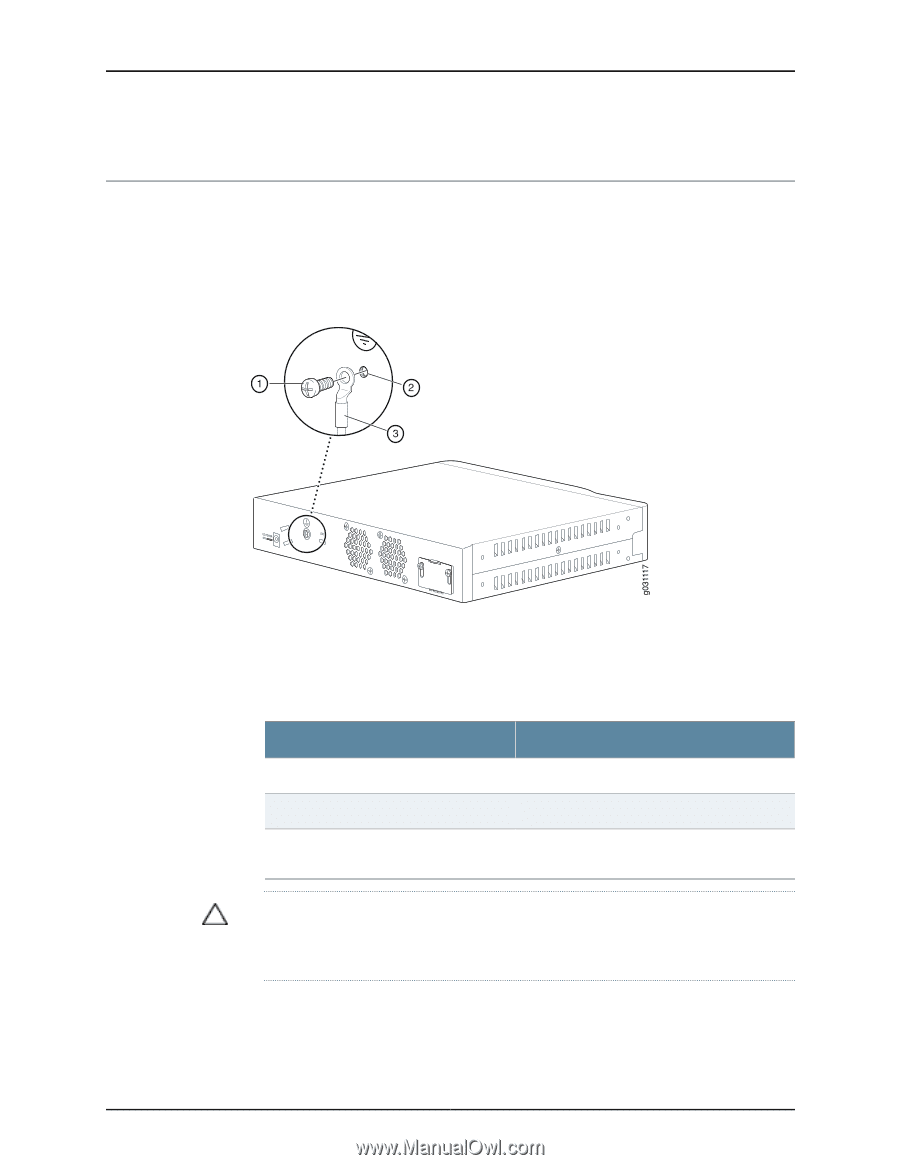
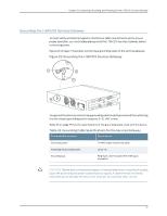
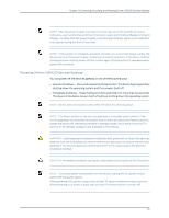
Chapter 13: Connecting, Grounding, and Powering On the J-SRX210 Services Gateway Grounding the J-SRX210 Services Gateway To meet safety and electromagnetic interference (EMI) requirements and to ensure proper operation, you must adequately ground the J-SRX210 Services Gateway before connecting power. Figure 23 on page 77 illustrates connecting a grounding cable to the services gateway. Figure 23: Grounding the J-SRX210 Services Gateway You ground the device by connecting a grounding cable to earth ground and then attaching it to the chassis grounding points using one 6-32 UNC screw. Table 32 on page 77 lists the specifications of the grounding cable used with the device. Table 32: Grounding Cable Specifications for the Services Gateway Grounding Requirement Specification Grounding cable 14 AWG single-strand wire cable Amperage of grounding cable Up to 4 A Grounding lug Ring-type, vinyl-insulated TV14-6R lug or equivalent CAUTION: Before device installation begins, a licensed electrician must attach a cable lug to the grounding and power cables that you supply. A cable with an incorrectly attached lug can damage the device (for example, by causing a short circuit). 77
-
 1
1 -
2
-
3
-
4
-
5
-
6
-
7
-
8
-
9
-
10
-
11
-
12
-
13
-
14
-
15
-
16
-
17
-
18
-
19
-
20
-
21
-
22
-
23
-
24
-
25
-
26
-
27
-
28
-
29
-
30
-
31
-
32
-
33
-
34
-
35
-
36
-
37
-
38
-
39
-
40
-
41
-
42
-
43
-
44
-
45
-
46
-
47
-
48
-
49
-
50
-
51
-
52
-
53
-
54
-
55
-
56
-
57
-
58
-
59
-
60
-
61
-
62
-
63
-
64
-
65
-
66
-
67
-
68
-
69
-
70
-
71
-
72
-
73
-
74
-
75
-
76
-
77
-
78
-
79
-
80
-
81
-
82
-
83
-
84
-
85
-
86
-
87
-
 88
88 -
 89
89 -
 90
90 -
 91
91 -
 92
92 -
 93
93 -
 94
94 -
 95
95 -
 96
96 -
 97
97 -
 98
98 -
99
-
100
-
101
-
102
-
103
-
104
-
105
-
106
-
107
-
108
-
109
-
110
-
111
-
112
-
113
-
114
-
115
-
116
-
117
-
118
-
119
-
120
-
121
-
122
-
123
-
124
-
125
-
126
-
127
-
128
-
129
-
130
-
131
-
132
-
133
-
134
-
135
-
136
-
137
-
138
-
139
-
140
-
141
-
142
-
143
-
144
-
145
-
146
-
147
-
148
-
149
-
150
-
151
-
152
-
153
-
154
-
155
-
156
-
157
-
158
-
159
-
160
-
161
-
162
-
163
-
164
-
165
-
166
-
167
-
168
-
169
-
170
-
171
-
172
-
173
-
174
-
175
-
176
-
177
-
178
-
179
-
180
-
181
-
182
 |
 |