Dell PowerConnect J-SRX210 Hardware Guide - Page 165
RJ-11 Connector Pinouts for the J-SRX210 Services Gateway with Integrated Convergence Services FXO and FXS Ports
 |
View all Dell PowerConnect J-SRX210 manuals
Add to My Manuals
Save this manual to your list of manuals |
Page 165 highlights
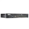
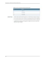
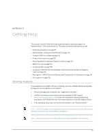
Appendix C: J-SRX210 Services Gateway Interface Cable Specifications and Connector Pinouts Figure 28: Console Cable Connector Table 49 on page 149 describes the RJ-45 connector pinouts for the console port. Table 49: RJ-45 Connector Pinouts for Services Gateway Console Port Pin Signal Description 1 RTS Request to Send 2 DTR Data Terminal Ready 3 TXD Transmit Data 4 Ground Signal Ground 5 Ground Signal Ground 6 RXD Receive Data 7 DSR/DCD Data Set Ready 8 CTS Clear to Send Related Topics • Interface Cable and Wire Specifications for the J-SRX210 Services Gateway on page 147 • RJ-45 Connector Pinouts for the J-SRX210 Services Gateway Ethernet Port on page 148 • RJ-45 Connector Pinouts for the J-SRX210 Services Gateway Console Port on page 148 • J-SRX210 Services Gateway Front Panel and Back Panel Views on page 9 RJ-11 Connector Pinouts for the J-SRX210 Services Gateway with Integrated Convergence Services FXO and FXS Ports The FXO and FXS ports use an RJ-11 cable. Table 50 on page 149 describes the RJ-11 connector pinouts. Table 50: RJ-11 Connector Pinouts Pin Signal 1 No connect 2 No connect 3 RJ P -Ring 149
-
 1
1 -
2
-
3
-
4
-
5
-
6
-
7
-
8
-
9
-
10
-
11
-
12
-
13
-
14
-
15
-
16
-
17
-
18
-
19
-
20
-
21
-
22
-
23
-
24
-
25
-
26
-
27
-
28
-
29
-
30
-
31
-
32
-
33
-
34
-
35
-
36
-
37
-
38
-
39
-
40
-
41
-
42
-
43
-
44
-
45
-
46
-
47
-
48
-
49
-
50
-
51
-
52
-
53
-
54
-
55
-
56
-
57
-
58
-
59
-
60
-
61
-
62
-
63
-
64
-
65
-
66
-
67
-
68
-
69
-
70
-
71
-
72
-
73
-
74
-
75
-
76
-
77
-
78
-
79
-
80
-
81
-
82
-
83
-
84
-
85
-
86
-
87
-
88
-
89
-
90
-
91
-
92
-
93
-
94
-
95
-
96
-
97
-
98
-
99
-
100
-
101
-
102
-
103
-
104
-
105
-
106
-
107
-
108
-
109
-
110
-
111
-
112
-
113
-
114
-
115
-
116
-
117
-
118
-
119
-
120
-
121
-
122
-
123
-
124
-
125
-
126
-
127
-
128
-
129
-
130
-
131
-
132
-
133
-
134
-
135
-
136
-
137
-
138
-
139
-
140
-
141
-
142
-
143
-
144
-
145
-
146
-
147
-
148
-
149
-
150
-
151
-
152
-
153
-
154
-
155
-
156
-
157
-
158
-
159
-
 160
160 -
 161
161 -
 162
162 -
 163
163 -
 164
164 -
 165
165 -
 166
166 -
 167
167 -
 168
168 -
 169
169 -
 170
170 -
171
-
172
-
173
-
174
-
175
-
176
-
177
-
178
-
179
-
180
-
181
-
182
 |
 |