Dell PowerConnect J-SRX240 Hardware Guide - Page 54
General Site Guidelines for Installing the J-SRX240 Services Gateway - review
 |
View all Dell PowerConnect J-SRX240 manuals
Add to My Manuals
Save this manual to your list of manuals |
Page 54 highlights
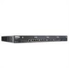
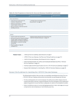
PowerConnect J-SRX240 Services Gateway Hardware Guide Table 18: Site Preparation Checklist for Services Gateway Installation (continued) Item or Task Additional Information Date and Notes Rack Installation • Verify that your rack meets the minimum requirements. • Plan the rack location, including required space clearances. • Secure the rack to the floor and the building structure. "J-SRX240 Services Gateway Rack Requirements" on page 39 Cables • Acquire cables and connectors. • Review the maximum distance allowed for each cable. Choose the length of cable based on the distance between the hardware components being connected. • Plan the cable routing and management. "Interface Cable and Wire Specifications for the J-SRX240 Services Gateway" on page 127 Related Topics • J-SRX240 Services Gateway Specifications on page 7 • J-SRX240 Services Gateway Site Electrical Wiring Guidelines on page 123 • J-SRX240 Services Gateway Rack Requirements on page 39 • Clearance Requirements for Airflow and Hardware Maintenance of the J-SRX240 Services Gateway on page 40 • Interface Cable and Wire Specifications for the J-SRX240 Services Gateway on page 127 • General Site Guidelines for Installing the J-SRX240 Services Gateway on page 38 General Site Guidelines for Installing the J-SRX240 Services Gateway The following precautions help you plan an acceptable operating environment for your J-SRX240 Services Gateway and avoid environmentally caused equipment failures: • For the cooling system to function properly, the airflow around the chassis must be unrestricted. Allow sufficient clearance between the front and back of the chassis and adjacent equipment. Ensure that there is adequate circulation in the installation location. • Follow the ESD procedures to avoid damaging equipment. Static discharge can cause components to fail completely or intermittently over time. 38
-
 1
1 -
2
-
3
-
4
-
5
-
6
-
7
-
8
-
9
-
10
-
11
-
12
-
13
-
14
-
15
-
16
-
17
-
18
-
19
-
20
-
21
-
22
-
23
-
24
-
25
-
26
-
27
-
28
-
29
-
30
-
31
-
32
-
33
-
34
-
35
-
36
-
37
-
38
-
39
-
40
-
41
-
42
-
43
-
44
-
45
-
46
-
47
-
48
-
 49
49 -
 50
50 -
 51
51 -
 52
52 -
 53
53 -
 54
54 -
 55
55 -
 56
56 -
 57
57 -
 58
58 -
 59
59 -
60
-
61
-
62
-
63
-
64
-
65
-
66
-
67
-
68
-
69
-
70
-
71
-
72
-
73
-
74
-
75
-
76
-
77
-
78
-
79
-
80
-
81
-
82
-
83
-
84
-
85
-
86
-
87
-
88
-
89
-
90
-
91
-
92
-
93
-
94
-
95
-
96
-
97
-
98
-
99
-
100
-
101
-
102
-
103
-
104
-
105
-
106
-
107
-
108
-
109
-
110
-
111
-
112
-
113
-
114
-
115
-
116
-
117
-
118
-
119
-
120
-
121
-
122
-
123
-
124
-
125
-
126
-
127
-
128
-
129
-
130
-
131
-
132
-
133
-
134
-
135
-
136
-
137
-
138
-
139
-
140
-
141
-
142
-
143
-
144
-
145
-
146
-
147
-
148
-
149
-
150
-
151
-
152
-
153
-
154
-
155
-
156
-
157
-
158
-
159
-
160
 |
 |