Dell PowerConnect J-SRX240 Hardware Guide - Page 56
Clearance Requirements for Airflow and Hardware Maintenance on the J-SRX240 Services Gateway
 |
View all Dell PowerConnect J-SRX240 manuals
Add to My Manuals
Save this manual to your list of manuals |
Page 56 highlights
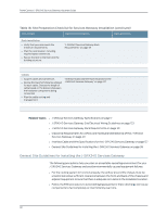
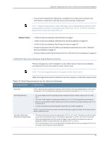
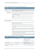
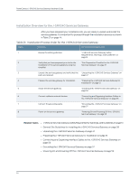
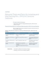
PowerConnect J-SRX240 Services Gateway Hardware Guide Table 19: Rack Requirements for the Services Gateway (continued) Rack Requirements Specifications Connecting to the Building Structure Always secure the rack in which you are installing the services gateway to the structure of the building. If your geographical area is subject to earthquakes, bolt the rack to the floor. For maximum stability, also secure the rack to ceiling brackets. Related Topics • General Site Guidelines for Installing the J-SRX240 Services Gateway on page 38 • Clearance Requirements for Airflow and Hardware Maintenance of the J-SRX240 Services Gateway on page 40 • J-SRX240 Services Gateway Network Cable Requirements and Specifications on page 41 • J-SRX240 Services Gateway Electrical and Power Requirements on page 41 Clearance Requirements for Airflow and Hardware Maintenance on the J-SRX240 Services Gateway When planning the installation site for the J-SRX240 Services Gateway, you need to allow sufficient clearance around the rack. When planning the installation site for the services gateway, consider the following: • For the cooling system to function properly, the airflow around the chassis must be unrestricted. • For service personnel to service the device, there must be adequate space at the front and back of the device. Allow at least 24 in. (61 cm) both in front of and behind the device. • If you are mounting the device in a rack with other equipment, or if you are placing it on the desktop near other equipment, ensure that the exhaust from other equipment does not blow into the intake vents of the chassis. Table 20 on page 40 provides information on the clearance requirements for maintaining the optimum airflow and the distances for facilitating easy maintenance of the device. Table 20: Clearance Requirements for the Services Gateway Location Recommended Clearance Requirement for Clearance Front of the chassis Rear of the chassis 2.5 in. (6.35 cm) 2.5 in. (6.35 cm) Space for service personnel to remove and install hardware components NOTE: More space is required for installing and removing Mini-PIMs. Space for service personnel to remove and install hardware components Between front-mounting flange and rack 2.5 in. (6.35 cm) or cabinet edge Space for cable management and organization 40
-
 1
1 -
2
-
3
-
4
-
5
-
6
-
7
-
8
-
9
-
10
-
11
-
12
-
13
-
14
-
15
-
16
-
17
-
18
-
19
-
20
-
21
-
22
-
23
-
24
-
25
-
26
-
27
-
28
-
29
-
30
-
31
-
32
-
33
-
34
-
35
-
36
-
37
-
38
-
39
-
40
-
41
-
42
-
43
-
44
-
45
-
46
-
47
-
48
-
49
-
50
-
 51
51 -
 52
52 -
 53
53 -
 54
54 -
 55
55 -
 56
56 -
 57
57 -
 58
58 -
 59
59 -
 60
60 -
 61
61 -
62
-
63
-
64
-
65
-
66
-
67
-
68
-
69
-
70
-
71
-
72
-
73
-
74
-
75
-
76
-
77
-
78
-
79
-
80
-
81
-
82
-
83
-
84
-
85
-
86
-
87
-
88
-
89
-
90
-
91
-
92
-
93
-
94
-
95
-
96
-
97
-
98
-
99
-
100
-
101
-
102
-
103
-
104
-
105
-
106
-
107
-
108
-
109
-
110
-
111
-
112
-
113
-
114
-
115
-
116
-
117
-
118
-
119
-
120
-
121
-
122
-
123
-
124
-
125
-
126
-
127
-
128
-
129
-
130
-
131
-
132
-
133
-
134
-
135
-
136
-
137
-
138
-
139
-
140
-
141
-
142
-
143
-
144
-
145
-
146
-
147
-
148
-
149
-
150
-
151
-
152
-
153
-
154
-
155
-
156
-
157
-
158
-
159
-
160
 |
 |