Dell PowerConnect J-SRX240 Hardware Guide - Page 55
J-SRX240 Services Gateway Rack Requirements, Table 19: Rack Requirements for the Services Gateway
 |
View all Dell PowerConnect J-SRX240 manuals
Add to My Manuals
Save this manual to your list of manuals |
Page 55 highlights
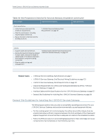
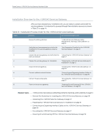
Chapter 6: Preparing the Site for the J-SRX240 Services Gateway Installation • Ensure that the blank Mini-PIM panel is installed in the empty slot to prevent any interruption or reduction in the flow of air across internal components. NOTE: Install the device only in restricted areas, such as dedicated equipment rooms and equipment closets, in accordance with Articles 110-16, 110-17, and 110-18 of the National Electrical Code, ANSI/NFPA 70. Related Topics • J-SRX240 Services Gateway Specifications on page 7 • J-SRX240 Services Gateway Site Electrical Wiring Guidelines on page 123 • J-SRX240 Services Gateway Rack Requirements on page 39 • Clearance Requirements for Airflow and Hardware Maintenance on the J-SRX240 Services Gateway on page 40 • Interface Cable and Wire Specifications for the J-SRX240 Services Gateway on page 127 J-SRX240 Services Gateway Rack Requirements The services gateway can be installed in a rack. Many types of racks are acceptable, including front-mount racks and four-post (telco) racks. NOTE: The services gateway does not support center-mount racks. Table 19 on page 39 provides the details on rack size, clearance, and airflow requirements. Table 19: Rack Requirements for the Services Gateway Rack Requirements Specifications Rack Size A 19 in. (48.3 cm) rack as defined in Cabinets, Racks, Panels, and Associated Equipment (document number EIA-310-D) published by the Electronics Industry Association (http://www.eia.org). Rack Requirements Spacing of Mounting Bracket and Flange Holes • The outer edges of the mounting brackets extend the width of either chassis to 19 in. (48.3 cm). • The front of the chassis extends approximately 0.5 in. (1.27 cm) beyond the mounting ears. • Maximum permissible ambient temperature when two devices are placed side by side in a 19 in. rack is 40ο C. • In a rack, two devices should be placed in alternate slots and not adjacent. NOTE: If you use a front-mount rack, we recommend you support the back of the device with a shelf or other structure. • The holes within each rack set are spaced at 1 U [1.75 in. (4.5 cm)]. The device can be mounted in any rack that provides holes or hole patterns spaced at 1-U [1.75 in. (4.5 cm)] increments. • The mounting brackets and front-mount flanges used to attach the chassis to a rack are designed to fasten to holes spaced at rack distances of 1 U (1.75 in.). • The mounting holes in the mounting brackets provided with the device are spaced 1.25 in. (3.2 cm) apart (top and bottom mounting hole). 39
-
 1
1 -
2
-
3
-
4
-
5
-
6
-
7
-
8
-
9
-
10
-
11
-
12
-
13
-
14
-
15
-
16
-
17
-
18
-
19
-
20
-
21
-
22
-
23
-
24
-
25
-
26
-
27
-
28
-
29
-
30
-
31
-
32
-
33
-
34
-
35
-
36
-
37
-
38
-
39
-
40
-
41
-
42
-
43
-
44
-
45
-
46
-
47
-
48
-
49
-
 50
50 -
 51
51 -
 52
52 -
 53
53 -
 54
54 -
 55
55 -
 56
56 -
 57
57 -
 58
58 -
 59
59 -
 60
60 -
61
-
62
-
63
-
64
-
65
-
66
-
67
-
68
-
69
-
70
-
71
-
72
-
73
-
74
-
75
-
76
-
77
-
78
-
79
-
80
-
81
-
82
-
83
-
84
-
85
-
86
-
87
-
88
-
89
-
90
-
91
-
92
-
93
-
94
-
95
-
96
-
97
-
98
-
99
-
100
-
101
-
102
-
103
-
104
-
105
-
106
-
107
-
108
-
109
-
110
-
111
-
112
-
113
-
114
-
115
-
116
-
117
-
118
-
119
-
120
-
121
-
122
-
123
-
124
-
125
-
126
-
127
-
128
-
129
-
130
-
131
-
132
-
133
-
134
-
135
-
136
-
137
-
138
-
139
-
140
-
141
-
142
-
143
-
144
-
145
-
146
-
147
-
148
-
149
-
150
-
151
-
152
-
153
-
154
-
155
-
156
-
157
-
158
-
159
-
160
 |
 |