HP 750c HP DesignJet 700 user guide - Page 27
Use slot 3
 |
View all HP 750c manuals
Add to My Manuals
Save this manual to your list of manuals |
Page 27 highlights
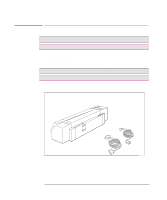
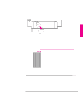
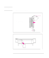
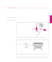
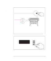
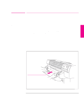
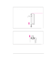
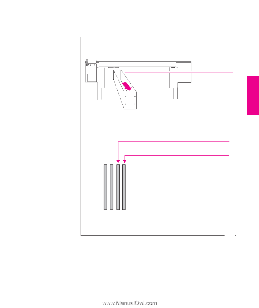
SETUP 1 Setting Up The Plotter Task 2: (Optional) Install Memory Expansion Modules 2 Using a flat-blade screwdriver, unscrew the cover plate at the back of the plotter, and remove it. Unscrew only the four screws on the cover plate. Cover plate The two slots on the right are for memory expansion modules. Use slot 3 first, and then slot 4. Slot for first memory module installed Slot for second memory module installed 1 2 34 If your plotter has only one memory module, it must be in slot number 3. 1845a 1-7
-
 1
1 -
2
-
3
-
4
-
5
-
6
-
7
-
8
-
9
-
10
-
11
-
12
-
13
-
14
-
15
-
16
-
17
-
18
-
19
-
20
-
21
-
 22
22 -
 23
23 -
 24
24 -
 25
25 -
 26
26 -
 27
27 -
 28
28 -
 29
29 -
 30
30 -
 31
31 -
 32
32 -
33
-
34
-
35
-
36
-
37
-
38
-
39
-
40
-
41
-
42
-
43
-
44
-
45
-
46
-
47
-
48
-
49
-
50
-
51
-
52
-
53
-
54
-
55
-
56
-
57
-
58
-
59
-
60
-
61
-
62
-
63
-
64
-
65
-
66
-
67
-
68
-
69
-
70
-
71
-
72
-
73
-
74
-
75
-
76
-
77
-
78
-
79
-
80
-
81
-
82
-
83
-
84
-
85
-
86
-
87
-
88
-
89
-
90
-
91
-
92
-
93
-
94
-
95
-
96
-
97
-
98
-
99
-
100
-
101
-
102
-
103
-
104
-
105
-
106
-
107
-
108
-
109
-
110
-
111
-
112
-
113
-
114
-
115
-
116
-
117
-
118
-
119
-
120
-
121
-
122
-
123
-
124
-
125
-
126
-
127
-
128
-
129
-
130
-
131
-
132
-
133
-
134
-
135
-
136
-
137
-
138
-
139
-
140
-
141
-
142
-
143
-
144
-
145
-
146
-
147
-
148
-
149
-
150
-
151
-
152
-
153
-
154
-
155
-
156
-
157
-
158
-
159
-
160
-
161
-
162
-
163
-
164
-
165
-
166
-
167
-
168
-
169
-
170
-
171
-
172
-
173
-
174
-
175
-
176
-
177
-
178
-
179
-
180
-
181
-
182
-
183
-
184
-
185
-
186
-
187
-
188
-
189
-
190
-
191
-
192
-
193
-
194
-
195
-
196
-
197
-
198
-
199
-
200
-
201
-
202
-
203
-
204
-
205
-
206
-
207
-
208
-
209
-
210
-
211
-
212
-
213
-
214
-
215
-
216
-
217
-
218
-
219
-
220
-
221
-
222
 |
 |
1-7
2
Using a flat-blade screwdriver, unscrew the cover plate at the back of the
plotter, and remove it.
Unscrew only the four screws on the cover plate.
The two slots
on the
right
are for memory expansion modules.
Use slot 3
first, and then slot 4.
Slot for second memory module installed
Slot for first memory module installed
If your plotter has only one memory module, it must be in slot number 3.
1
2
3
4
Cover plate
1845a
SETUP
1
Setting Up The Plotter
Task 2: (Optional) Install Memory Expansion Modules