HP 750c HP DesignJet 700 user guide - Page 33
Insert the spindle so that the large media stop A is to the right and
 |
View all HP 750c manuals
Add to My Manuals
Save this manual to your list of manuals |
Page 33 highlights
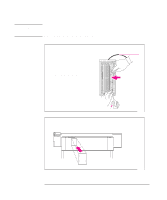
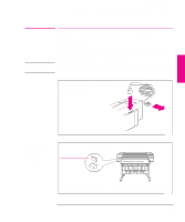
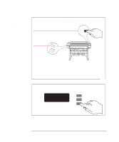
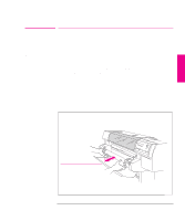
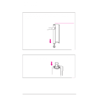
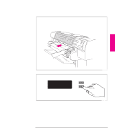
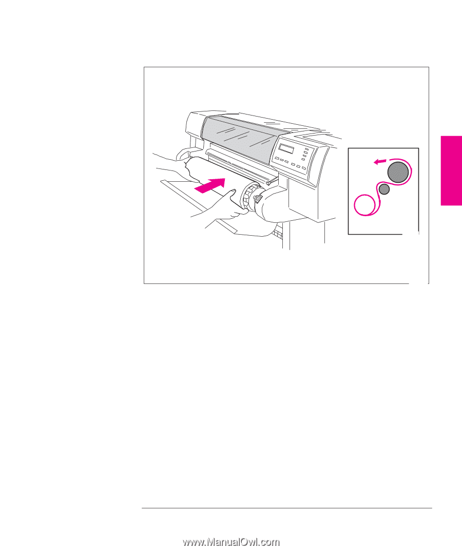
Setting Up the Plotter Task 4: Load Media 5 Insert the spindle so that the large media stop (A) is to the right and the small end cap (B) to the left. Push in firmly on both ends. Be sure the media remains flush against the media stop. B A A Media path 0017 The relationship of the media to the roller must be as shown in the diagram above. 1837 6 Check the leading edge as it unwinds from the spool. If it is uneven, trim it as explained in step 7. Otherwise go to step 8. SETUP 1 1-13
-
 1
1 -
2
-
3
-
4
-
5
-
6
-
7
-
8
-
9
-
10
-
11
-
12
-
13
-
14
-
15
-
16
-
17
-
18
-
19
-
20
-
21
-
22
-
23
-
24
-
25
-
26
-
27
-
 28
28 -
 29
29 -
 30
30 -
 31
31 -
 32
32 -
 33
33 -
 34
34 -
 35
35 -
 36
36 -
 37
37 -
 38
38 -
39
-
40
-
41
-
42
-
43
-
44
-
45
-
46
-
47
-
48
-
49
-
50
-
51
-
52
-
53
-
54
-
55
-
56
-
57
-
58
-
59
-
60
-
61
-
62
-
63
-
64
-
65
-
66
-
67
-
68
-
69
-
70
-
71
-
72
-
73
-
74
-
75
-
76
-
77
-
78
-
79
-
80
-
81
-
82
-
83
-
84
-
85
-
86
-
87
-
88
-
89
-
90
-
91
-
92
-
93
-
94
-
95
-
96
-
97
-
98
-
99
-
100
-
101
-
102
-
103
-
104
-
105
-
106
-
107
-
108
-
109
-
110
-
111
-
112
-
113
-
114
-
115
-
116
-
117
-
118
-
119
-
120
-
121
-
122
-
123
-
124
-
125
-
126
-
127
-
128
-
129
-
130
-
131
-
132
-
133
-
134
-
135
-
136
-
137
-
138
-
139
-
140
-
141
-
142
-
143
-
144
-
145
-
146
-
147
-
148
-
149
-
150
-
151
-
152
-
153
-
154
-
155
-
156
-
157
-
158
-
159
-
160
-
161
-
162
-
163
-
164
-
165
-
166
-
167
-
168
-
169
-
170
-
171
-
172
-
173
-
174
-
175
-
176
-
177
-
178
-
179
-
180
-
181
-
182
-
183
-
184
-
185
-
186
-
187
-
188
-
189
-
190
-
191
-
192
-
193
-
194
-
195
-
196
-
197
-
198
-
199
-
200
-
201
-
202
-
203
-
204
-
205
-
206
-
207
-
208
-
209
-
210
-
211
-
212
-
213
-
214
-
215
-
216
-
217
-
218
-
219
-
220
-
221
-
222
 |
 |
1-13
5
Insert the spindle so that the large media stop (A) is to the right and the
small end cap (B) to the left. Push in firmly on both ends. Be sure the
media remains flush against the media stop.
The relationship of the media to the roller must be as shown in the
diagram above.
A
B
A
Media path
1837
0017
6
Check the leading edge as it unwinds from the spool. If it is uneven, trim it as
explained in step 7.
Otherwise go to step 8.
SETUP
1
Setting Up the Plotter
Task 4: Load Media