HP 750c HP DesignJet 755CM Printer User's Guide - C3198-60051 - Page 195
Interface Specifications
 |
View all HP 750c manuals
Add to My Manuals
Save this manual to your list of manuals |
Page 195 highlights
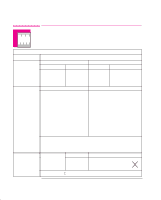
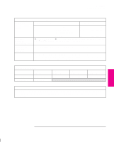
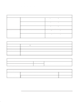
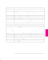
Reference Interface Specifications Interface Specifications Below are the parallel and serial interface specifications. For specifications of the HP JetDirect Network interface, see the JetDirect Print Server documentation supplied with this printer. Parallel (Bi-Tronics/Centronics) Interface The connector on the printer is 36-pin female. Most existing parallel cables support Bi-Tronics communication, but for use with this printer, the cable must meet the specification in this table. Pin Wire/Signal Name 1 Strobe 2 ... 9 D0 ... D7 (data lines) 10 Ack 11 Busy 12 PError 13 Select (SelectOut) 14 AutoFd 16 GND 19 ... 30 GND 31 Init 32 Fault 36 SelectIn Source computer both printer printer printer printer computer computer printer computer Serial (RS-232-C) Interface The connector on the printer is 25-pin female. The printer is configured as DTE (data terminal equipment). Data is transmitted on Pin 2 and received on Pin 3. Pin Wire/Signal Name 1 Protective Ground 2 Transmitted Data 3 Received Data 4 Request to Send 6 Data Set Ready 7 Signal Ground 20 Data Terminal Ready Source DTE DCE DTE DCE DTE REFERENCE 11 11-7
-
 1
1 -
2
-
3
-
4
-
5
-
6
-
7
-
8
-
9
-
10
-
11
-
12
-
13
-
14
-
15
-
16
-
17
-
18
-
19
-
20
-
21
-
22
-
23
-
24
-
25
-
26
-
27
-
28
-
29
-
30
-
31
-
32
-
33
-
34
-
35
-
36
-
37
-
38
-
39
-
40
-
41
-
42
-
43
-
44
-
45
-
46
-
47
-
48
-
49
-
50
-
51
-
52
-
53
-
54
-
55
-
56
-
57
-
58
-
59
-
60
-
61
-
62
-
63
-
64
-
65
-
66
-
67
-
68
-
69
-
70
-
71
-
72
-
73
-
74
-
75
-
76
-
77
-
78
-
79
-
80
-
81
-
82
-
83
-
84
-
85
-
86
-
87
-
88
-
89
-
90
-
91
-
92
-
93
-
94
-
95
-
96
-
97
-
98
-
99
-
100
-
101
-
102
-
103
-
104
-
105
-
106
-
107
-
108
-
109
-
110
-
111
-
112
-
113
-
114
-
115
-
116
-
117
-
118
-
119
-
120
-
121
-
122
-
123
-
124
-
125
-
126
-
127
-
128
-
129
-
130
-
131
-
132
-
133
-
134
-
135
-
136
-
137
-
138
-
139
-
140
-
141
-
142
-
143
-
144
-
145
-
146
-
147
-
148
-
149
-
150
-
151
-
152
-
153
-
154
-
155
-
156
-
157
-
158
-
159
-
160
-
161
-
162
-
163
-
164
-
165
-
166
-
167
-
168
-
169
-
170
-
171
-
172
-
173
-
174
-
175
-
176
-
177
-
178
-
179
-
180
-
181
-
182
-
183
-
184
-
185
-
186
-
187
-
188
-
189
-
 190
190 -
 191
191 -
 192
192 -
 193
193 -
 194
194 -
 195
195 -
 196
196 -
 197
197 -
 198
198 -
 199
199 -
 200
200 -
201
-
202
-
203
-
204
-
205
-
206
-
207
-
208
-
209
-
210
-
211
-
212
-
213
-
214
-
215
-
216
-
217
-
218
-
219
-
220
 |
 |