HP Integrity rx2620 Installation Guide, Third Edition - HP Integrity rx2620 (A
HP Integrity rx2620 Manual
 |
View all HP Integrity rx2620 manuals
Add to My Manuals
Save this manual to your list of manuals |
HP Integrity rx2620 manual content summary:
- HP Integrity rx2620 | Installation Guide, Third Edition - HP Integrity rx2620 (A - Page 1
Installation Guide HP Integrity rx2620 Server Manufacturing Part Number: AD117-9001A Third Edition August 2006 © Copyright 2006 Hewlett-Packard Development Company, L.P. - HP Integrity rx2620 | Installation Guide, Third Edition - HP Integrity rx2620 (A - Page 2
accompanying such products and services. Nothing herein should be construed as constituting an additional warranty. HP shall not be liable for technical or editorial errors or omissions contained herein. Printed in the USA. Intel, Intel Inside, Itanium, and the Intel Inside logo are trademarks - HP Integrity rx2620 | Installation Guide, Third Edition - HP Integrity rx2620 (A - Page 3
17 Server Components 17 Itanium-2 Processors 17 Memory 18 PCI Riser 18 Internal Core I/O 18 External Core I/O 18 Power Supply Unit 18 System Board Manageability 19 Enhanced Server Manageability Using the Integrated Lights Out Management Processor 19 Hard Disk Drives 19 System Board - HP Integrity rx2620 | Installation Guide, Third Edition - HP Integrity rx2620 (A - Page 4
Cover 36 Installing Internal Hard Disk Drives 37 Installing Additional System Memory 40 Supported DIMM Sizes 40 Installing System Memory 41 Installing Additional PCI Cards 43 Removing the PCI Cage 44 Installing PCI Cards 46 Installing an Additional Power Supply 47 Installing an Additional - HP Integrity rx2620 | Installation Guide, Third Edition - HP Integrity rx2620 (A - Page 5
Available 104 Operating System Does Not Boot 104 Operating System Boots with Problems 104 Intermittent Server Problems 105 DVD Problems Occur 105 Hard Drive Problems Occur 105 Console Problems Occur 106 Downloading and Installing the Latest Version of the Firmware 106 Downloading the Latest - HP Integrity rx2620 | Installation Guide, Third Edition - HP Integrity rx2620 (A - Page 6
Contents 6 - HP Integrity rx2620 | Installation Guide, Third Edition - HP Integrity rx2620 (A - Page 7
1. Publishing History Details 11 Table 2. HP-UX 11i Releases 13 Table 1-1. Server Dimensions 17 Table 1-2. Memory Array Capacities 23 Table 1-3. Installation Sequence Checklist 28 Table 5-1. Power States 58 Table 6-1. Setup Checklist 62 Table 6-2. Console Connection Matrix 64 Table 6-3. LAN - HP Integrity rx2620 | Installation Guide, Third Edition - HP Integrity rx2620 (A - Page 8
Tables 8 - HP Integrity rx2620 | Installation Guide, Third Edition - HP Integrity rx2620 (A - Page 9
Cover 36 Figure 3-5. Front View of the HP Integrity rx2620 Server 37 Figure 3-6. Lock/Unlock Lever 38 Figure 3-7. Filler Removal from Slot 38 Figure 3-8. Disk Drive Installation 39 Figure 3-9. DIMM Slot Identification 41 Figure 3-10. Removing the Memory Airflow Guide 42 Figure 3-11. Inserting - HP Integrity rx2620 | Installation Guide, Third Edition - HP Integrity rx2620 (A - Page 10
Figures 10 - HP Integrity rx2620 | Installation Guide, Third Edition - HP Integrity rx2620 (A - Page 11
product and support information for authorized service providers, system administrators, and HP support personnel. This document is not a tutorial. New and Changed Information in This Edition • This document is being updated as part of upgrading the HP Integrity rx2620 server. Publishing History - HP Integrity rx2620 | Installation Guide, Third Edition - HP Integrity rx2620 (A - Page 12
this chapter to learn about the features and specifications of the HP Integrity rx2620 server. Chapter 2 Unpack and Inspect the Server Use this chapter to inspect the server in its shipping packaging, and unpacking it. Chapter 3 Installing Additional Components Use this chapter fro procedures on - HP Integrity rx2620 | Installation Guide, Third Edition - HP Integrity rx2620 (A - Page 13
11.20 B.11.22 B.11.23 Release Name HP-UX 11i v1 HP-UX 11i v1.5 HP-UX 11i v1.6 HP-UX 11i v2.0 Supported Processor Architecture PA-RISC Intel® Itanium® Intel Itanium Intel Itanium Related Documents You can find other information on HP server hardware management, Microsoft® Windows®, and diagnostic - HP Integrity rx2620 | Installation Guide, Third Edition - HP Integrity rx2620 (A - Page 14
for HP Technical Support: http://us-support2.external.hp.com/ Books about HP-UX Published by Prentice Hall The http://www.hp.com/hpbooks/ Web site lists the HP books that Prentice Hall currently publishes, such as HP-UX books including: • HP-UX 11i System Administration Handbook http://www.hp.com - HP Integrity rx2620 | Installation Guide, Third Edition - HP Integrity rx2620 (A - Page 15
The HP Integrity rx2620 server is a 2-socket server based on the Itanium processor architecture. The server supports the following operating systems: Microsoft Windows, HP-UX, Linux, and OpenVMS. The server is available in either rack-mount or tower configurations. The server accommodates - HP Integrity rx2620 | Installation Guide, Third Edition - HP Integrity rx2620 (A - Page 16
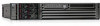
1-2 HP Integrity rx2620 Server (front view with bezel removed) Figure 1-3 HP Integrity rx2620 Server (rear view) WARNING Unplug all power cords from system before servicing PWR 2 PWR 1 Management Card LAN 10/100 VGA Automatic Internal SCSI Termination SCSI LVD/SE LAN Gb A MP RESET CONSOLE - HP Integrity rx2620 | Installation Guide, Third Edition - HP Integrity rx2620 (A - Page 17
The following components make up the HP Integrity rx2620 server: • "Itanium-2 Processors" on page 17 • "Memory" on page 18 • "PCI Riser" on page 18 • "Internal Core I/O" on page 18 • "External Core I/O" on page 18 • "Power Supply Unit" on page 18 • "System Board Manageability" on page 19 • "Enhanced - HP Integrity rx2620 | Installation Guide, Third Edition - HP Integrity rx2620 (A - Page 18
ports, 16550 compatible Power Supply Unit • 600 W output power • The power supply is split in a front-end block (the actual power supply case) that converts the line voltage into a high DC voltage. Back-end voltage regulation modules (on the system board) step down the front end DC voltage to the - HP Integrity rx2620 | Installation Guide, Third Edition - HP Integrity rx2620 (A - Page 19
all consoles • VGA and 2D graphics display • Advanced Features: - Secure Shell (SSH) access - Group actions through the HP Systems Insight Manager (HPSIM) - Directory-based authentication and authorization (LDAP) Hard Disk Drives The following hard disk drives are supported by the rx2620 server - HP Integrity rx2620 | Installation Guide, Third Edition - HP Integrity rx2620 (A - Page 20
system board and descriptions of key components (integrated circuits) on the board. Figure 1-4 shows a block diagram of the rx2620 server. Figure 1-4 System Block Diagram Itanium-2 IPF Itanium log) BMC FLASH 1MB I2C etc... LED STATUS PANEL LOCATOR DIAG LEDs ON-OFF LAN Activity ROPE 0 ASIC - HP Integrity rx2620 | Installation Guide, Third Edition - HP Integrity rx2620 (A - Page 21
and Memory Controller The HP Integrity rx2620 server supports the following features of the ZX1 I/O and memory controller chip: • 8.5 Gb/s peak I/O bandwidth • Seven communication paths • Peak memory bandwidth of 8.5 Gb/s. • Two memory cells, 144 data bits each. System Memory The memory subsystem - HP Integrity rx2620 | Installation Guide, Third Edition - HP Integrity rx2620 (A - Page 22
System Board Components The minimum amount of memory supported by the server is 1 GB (four 256 MB modules). The maximum amount of memory supported by the server is 32 GB (eight 4 GB modules). This design does not support any non industry standard DDR DIMMs. Only qualified DIMMs are supported - HP Integrity rx2620 | Installation Guide, Third Edition - HP Integrity rx2620 (A - Page 23
PCI-X 66 MHz to 133 MHz, 32 or 64 data bit support • Uses 3.3 V PCI only, and it does not support 5 V PCI • Optimizes for DMA performance • Supports 3.3 V or Universal keyed PCI cards. 5 V keyed PCI cards are not supported • Supports up to four PCI sockets Processor Dependent Hardware Controller The - HP Integrity rx2620 | Installation Guide, Third Edition - HP Integrity rx2620 (A - Page 24
diagnostics, console support, configuration management, hardware management, and troubleshooting. The BMC provides the following: • Compliance with IPMI 1.0 • Tachometer inputs for fan speed monitoring • Pulse width modulator outputs for fan speed control • Push-button inputs for front panel buttons - HP Integrity rx2620 | Installation Guide, Third Edition - HP Integrity rx2620 (A - Page 25
flat pack (LQFP) package • Firmware is provided for the following Specification and is hard-wired to PCI ID 1 which corresponds to bit 17 of the PCI AD bus. IDE Interface The IDE controller (PCI649) supports the ATAPI zero to five modes (from 16 to 100 Mb/s). The usable speed on this system - HP Integrity rx2620 | Installation Guide, Third Edition - HP Integrity rx2620 (A - Page 26
. Event IDs for Errors and Events The system firmware generates event IDs for errors, events, and forward progress to the MP through common shared memory. The MP interprets and stores event IDs. Reviewing these events helps you diagnose and troubleshoot problems with the server. 26 Chapter 1 - HP Integrity rx2620 | Installation Guide, Third Edition - HP Integrity rx2620 (A - Page 27
and to prevent damage to the server: • When removing or installing any server component, follow the instructions provided in this guide. • If installing a hot-swappable or hot-pluggable component when power is applied (fans are running), reinstall the server cover immediately to prevent overheating - HP Integrity rx2620 | Installation Guide, Third Edition - HP Integrity rx2620 (A - Page 28
Connection and Setup," on page 61. 6 Power on the server. See Chapter 7, "Powering On the Server," on page 73. 7 Access the host console. See Chapter 8, "Accessing the Host Console," on page 75. 8 Boot the operating system. See Chapter 9, "Booting the Operating System," on page 79. 9 Verify the - HP Integrity rx2620 | Installation Guide, Third Edition - HP Integrity rx2620 (A - Page 29
2 Unpacking and Inspecting the Server This chapter describes procedures performed before installation. Ensure that you have adequately prepared your environment for your new server, received the components that you ordered, and verified that the server and its containers are in good condition after - HP Integrity rx2620 | Installation Guide, Third Edition - HP Integrity rx2620 (A - Page 30
specifications and power requirements have been met. • Validate server physical space requirements. • Confirm environmental requirements. For more information on server electrical, physical space, and environmental requirements, refer to the HP Integrity rx2620 Site Preparation Guide. Inspecting - HP Integrity rx2620 | Installation Guide, Third Edition - HP Integrity rx2620 (A - Page 31
your HP customer service representative. The service representative initiates appropriate action through the transport carrier or the factory and assists you in returning the equipment. Unloading the Server with a Lifter To unload the server from the pallet using a lifter (if necessary), perform - HP Integrity rx2620 | Installation Guide, Third Edition - HP Integrity rx2620 (A - Page 32
Unpacking and Inspecting the Server Checking the Inventory 32 Chapter 2 - HP Integrity rx2620 | Installation Guide, Third Edition - HP Integrity rx2620 (A - Page 33
indicators of the server and instructions required in installing additional components and configuring the HP Integrity rx2620 server. This chapter addresses the following topics: • "Service Tools Required" on page 34 • "ESD Information" on page 34 • "Installing Internal Hard Disk Drives" on page 37 - HP Integrity rx2620 | Installation Guide, Third Edition - HP Integrity rx2620 (A - Page 34
safe handling of components and to prevent harm to both you and the HP server: • Use an anti-static wrist strap and a grounding mat, such as those included in the Electrically Conductive Field Service Grounding Kit (HP 9300-1155). • Handle accessory boards and components by the edges only. Do not - HP Integrity rx2620 | Installation Guide, Third Edition - HP Integrity rx2620 (A - Page 35
Installing Additional Components Removing and Replacing the Top Metal Cover Removing and Replacing the Top Metal Cover To access any of the internal components in the HP Integrity rx2620 server, you need to remove the top metal cover. The following procedures describe how to remove and replace the - HP Integrity rx2620 | Installation Guide, Third Edition - HP Integrity rx2620 (A - Page 36
mark on the optical drive bay. See Figure 3-3 for more information. Figure 3-3 Aligning the Top Metal Cover To replace cover, align front edge here then slide forward Front of server Step 2. Grasp the blue release lever and slide the top metal cover toward the front of the system until the lever - HP Integrity rx2620 | Installation Guide, Third Edition - HP Integrity rx2620 (A - Page 37
installing disk drives while the operating system is running. If the operating system does not support this feature, shut down the operating system before attempting this procedure. Failure to observe this caution results in system failure. Figure 3-5 Front View of the HP Integrity rx2620 Server - HP Integrity rx2620 | Installation Guide, Third Edition - HP Integrity rx2620 (A - Page 38
Hard Disk Drives To install a hard disk drive when the drive bay is locked, perform the following steps: Step 1. Remove the top metal cover. See "Removing the Top Metal Cover" on page 35. Step 2. Locate the Lock/Unlock lever located between the drive bay and the side of the server at the front - HP Integrity rx2620 | Installation Guide, Third Edition - HP Integrity rx2620 (A - Page 39
ejection handle to the open position. Step 6. Slide the hard disk drive into the slot until it is nearly seated. Figure 3-8 shows the installation of a hard disk drive. Figure 3-8 Disk Drive Installation Front of server Step 7. Close the drive ejector handle by pushing it inward until it clicks - HP Integrity rx2620 | Installation Guide, Third Edition - HP Integrity rx2620 (A - Page 40
Installing Additional Components Installing Additional System Memory Installing Additional System Memory The HP Integrity rx2620 server has 12 memory sockets for installing DDR SDRAM memory modules (DIMMs). These DIMMs can either be 256 MB, 512 MB, 1 GB, 2 GB, or 4GB. The system supports memory - HP Integrity rx2620 | Installation Guide, Third Edition - HP Integrity rx2620 (A - Page 41
Pair 5 (4A & 4B) Pair 3 (2A & 2B) Front of server Quad 1 = Pair 1 & Pair 2 Quad 2 = Pair 3 & Pair 4 Quad 3 = Pair 5 & Pair 6 Installing System Memory You must load the memory modules in the correct order: • You must install the DIMMs in the HP Integrity rx2620 server in matched quads. Two matched - HP Integrity rx2620 | Installation Guide, Third Edition - HP Integrity rx2620 (A - Page 42
module sizes, as long as DIMMs in each quad match, unless you are using 4 GB DIMMs. If you install 4 GB DIMMS, the only configurations allowed are four or eight 4 GB DIMMs. For example: • On HP Integrity rx2620 servers, it is acceptable to load a quad of 256 MB DIMMs in quad 1 (slots 0A, 0B, 1A and - HP Integrity rx2620 | Installation Guide, Third Edition - HP Integrity rx2620 (A - Page 43
This section explains how to access the PCI cage, as well as how to install accessory cards. WARNING Ensure that the system is powered down and all power sources have been disconnected from the server prior to removing or replacing a processor. Voltages are present at various locations within the - HP Integrity rx2620 | Installation Guide, Third Edition - HP Integrity rx2620 (A - Page 44
can be installed in the rx2620 server at any HP Authorized Service Provider. Observe all ESD safety precautions before attempting this procedure. Failure to follow ESD safety precautions could result in damage to the server. Removing the PCI Cage To remove the PCI cage from the server, perform - HP Integrity rx2620 | Installation Guide, Third Edition - HP Integrity rx2620 (A - Page 45
Figure 3-12 Removing the PCI Cage Installing Additional Components Installing Additional PCI Cards Front of server Step 3. Grasp the PCI cage cover and slide it away from the bulkhead end of the cage, then lift the cover off. Figure 3-13 Removing the PCI Cage Cover Chapter 3 45 - HP Integrity rx2620 | Installation Guide, Third Edition - HP Integrity rx2620 (A - Page 46
this caution will result in system degradation or system failure. The HP Integrity rx2620 server has the following accessory card sockets bottom of cage). See the labels on the rear panel of the chassis for correct PCI slot number identification. Installing a PCI Card Step 1. Remove the top metal - HP Integrity rx2620 | Installation Guide, Third Edition - HP Integrity rx2620 (A - Page 47
" on page 36. Installing an Additional Power Supply The supported configuration of an HP Integrity rx2620 server requires a minimum of one power supply unit (PSU). You can install a second hot-swap PSU to provide redundant (N+1) capability. The power supplies in the HP server are hot-swappable. If - HP Integrity rx2620 | Installation Guide, Third Edition - HP Integrity rx2620 (A - Page 48
Installing an Additional Power Supply Step 1. Remove the front bezel from the system and remove the power supply filler panel. Figure 3-15 shows how to remove the power supply filler panel. Figure 3-15 Removing the Power Supply Filler Panel Power supply 1 Front of server Step 2. Open the power - HP Integrity rx2620 | Installation Guide, Third Edition - HP Integrity rx2620 (A - Page 49
system board. The system board can support either one or two processor. The CPU 0 socket is located to the right of the system board (closer to the server chassis) and the CPU 1 socket is located on the left of the system board near the memory DIMMs. In a single CPU configuration, you must install - HP Integrity rx2620 | Installation Guide, Third Edition - HP Integrity rx2620 (A - Page 50
will result in system failure. Ensure that all processors are rated for use at the same speed. Failure to observe this caution will result in performance degradation. Valid processors are identified in the Parts Information chapter of the HP Integrity rx2620 Maintenance Guide. Step 7. Remove the - HP Integrity rx2620 | Installation Guide, Third Edition - HP Integrity rx2620 (A - Page 51
Additional Components Installing an Additional Processor c. At the same time, grasp the back end of the airflow guide and lift the guide out of the system. Figure 3-19 Removing the Processor Airflow Guide Front of server Step 9. Unlock the zero insertion force (ZIF) socket processor locking - HP Integrity rx2620 | Installation Guide, Third Edition - HP Integrity rx2620 (A - Page 52
. The two alignment pins fit in the alignment holes on the system board processor mount. The turbo fan power cable must be positioned so that it is located on the side of the heatsink that faces the front of the server. Figure 3-21 shows the alignment pins on the processor. Figure 3-21 Alignment - HP Integrity rx2620 | Installation Guide, Third Edition - HP Integrity rx2620 (A - Page 53
Installing an Additional Processor Step 11. Use the special processor tool (P/N 5069-5441) shipped with your replacement processor assembly to lock the processor in place on the system Processor tool Front of server Step 12. Slide the sequencing retainer plate toward the front of the system. Figure - HP Integrity rx2620 | Installation Guide, Third Edition - HP Integrity rx2620 (A - Page 54
2 4 2 4 6 Step 14. Connect the processor power cable to the server power cable. Step 15. Connect the fan power cable to the system board. Step 16. Replace the processor airflow guide, and route the IDE and power cables as previously recorded. Step 17. Install the top metal cover, unless you are - HP Integrity rx2620 | Installation Guide, Third Edition - HP Integrity rx2620 (A - Page 55
into a Rack or Tower This chapter provides instructions on how to install the server into a rack or a tower mount configuration. The following sections are included in this chapter: • "Install the Server into a Rack" on page 56 • "Install the Server into a Tower Mount" on page 56 Chapter 4 55 - HP Integrity rx2620 | Installation Guide, Third Edition - HP Integrity rx2620 (A - Page 56
information describes how to install the server into an HP rack, or an approved non-HP rack. HP Rack HP Integrity entry-class servers that are installed into racks are shipped with equipment mounting slides. With each set of slides comes an installation guide: Installation Guide, Mid-Weight Slide - HP Integrity rx2620 | Installation Guide, Third Edition - HP Integrity rx2620 (A - Page 57
5 Connecting Cables This chapter describes the cables that you must connect to install the server. This chapter addresses the following topics: • "AC Input Power" on page 58 • "LAN" on page 60 Chapter 5 57 - HP Integrity rx2620 | Installation Guide, Third Edition - HP Integrity rx2620 (A - Page 58
cords are not plugged in. Table 5-1 lists the server power states. Table 5-1 Power States Power States Standby power Full power Off Power Cable Plugged Into Receptacle? Power Activated through the MP PC Command; or Front Panel Power Button Activated? Yes No Yes Yes No No AC Voltage DC - HP Integrity rx2620 | Installation Guide, Third Edition - HP Integrity rx2620 (A - Page 59
amber light is still present on the hard disk drives. Standby power is on at this point. Power Cord Retention The following procedure shows how to install the power cord retention clip onto the back of the server. Step 1. Unscrew the two #3 screws on the server AC area. See Figure 5-1 for the screw - HP Integrity rx2620 | Installation Guide, Third Edition - HP Integrity rx2620 (A - Page 60
for the server. Figure 5-3 Rear Panel LAN Ports WARNING Unplug all power cords from system before servicing PWR 2 PWR 1 iLO MP 10/100 LAN (optional) Management Card LAN 10/100 VGA Automatic Internal SCSI Termination SCSI LVD/SE LAN Gb A LAN Gb A 10/100/1000 LAN MP RESET CONSOLE / REMOTE - HP Integrity rx2620 | Installation Guide, Third Edition - HP Integrity rx2620 (A - Page 61
Connection and Setup Setting up the console involves the following: • Determining the physical access method to connect cables. There are two physical connections to the Integrity iLO MP: RS-232 and LAN. • Configuring the Integrity iLO MP and assigning an IP address if necessary. Though there - HP Integrity rx2620 | Installation Guide, Third Edition - HP Integrity rx2620 (A - Page 62
DNS • ARP Ping • RS-232 serial port 3 Log on to the iLO MP Log in to the iLO MP from a supported Web browser or command line using the default user name and password. 4 Change default user name and password Change the default user name and password on the administrator account to your predefined - HP Integrity rx2620 | Installation Guide, Third Edition - HP Integrity rx2620 (A - Page 63
Setup Flowchart Use this flowchart as a guide to assist in the iLO MP setup process. Figure 6-1 iLO MP Setup Flowchart Console Connection and Setup Setup Flowchart Chapter 6 63 - HP Integrity rx2620 | Installation Guide, Third Edition - HP Integrity rx2620 (A - Page 64
connection method. The iLO MP has a separate LAN port from the system LAN port. It requires a separate LAN drop, IP address, and networking information from that of the port used by the operating system. See your server installation guide for rear panel console connection port identification and - HP Integrity rx2620 | Installation Guide, Third Edition - HP Integrity rx2620 (A - Page 65
Connection Matrix (Continued) Operating System Console Connection Method Required Connection Components OpenVMS Local RS-232 serial port 1. M-cable: DB25 connector on one end, and three DB-9F connectors on the other end: Remote/modem port • Console • Remote • UPS 2. RS-232 DB-9F to DB-9F - HP Integrity rx2620 | Installation Guide, Third Edition - HP Integrity rx2620 (A - Page 66
Console Connection and Setup Configuring the iLO MP LAN Using DHCP and DNS Table 6-3 LAN DHCP-enabled servers with IP addresses, subnet masks, and gateway addresses. All HP Integrity entry class servers with the iLO MP are shipped from the factory with DHCP enabled. HP recommends using - HP Integrity rx2620 | Installation Guide, Third Edition - HP Integrity rx2620 (A - Page 67
using a PC that is connected to the network that is on the same physical subnet as the server. To configure a static IP address using the ARP Ping utility, follow these steps: Step 1. Obtain the iLO MP MAC address. To set the IP address using ARP, you must know the MAC address of - HP Integrity rx2620 | Installation Guide, Third Edition - HP Integrity rx2620 (A - Page 68
Console Connection and Setup Configuring the iLO MP LAN Using the RS-232 Serial Port IMPORTANT Make sure you obtain the MAC address to the iLO MP LAN and not the MAC address to the server core LAN. Step 2. Verify that an active LAN cable on the local subnet is connected to the iLO MP LAN - HP Integrity rx2620 | Installation Guide, Third Edition - HP Integrity rx2620 (A - Page 69
is configured appropriately. Supported terminal types are: instructions on how to configure the software options. Step 2. Use Table 6-2 to determine the required connection components, and the ports used to connect the server to the console device. Step 3. Connect the cables. a. Connect the DB25 end - HP Integrity rx2620 | Installation Guide, Third Edition - HP Integrity rx2620 (A - Page 70
. TIP For security reasons, HP strongly recommends you modify the default settings during the initial login session. See "Modifying User Accounts and Default Password" on page 70. Following is the MP Main Menu screen: MP MAIN MENU: CO: Console VFP: Virtual Front Panel CM: Command Menu CL - HP Integrity rx2620 | Installation Guide, Third Edition - HP Integrity rx2620 (A - Page 71
Login and password are case sensitive. Console Connection and Setup Additional Setup TIP For security reasons, HP strongly recommends you modify the default settings during the initial login session. Make the following changes using any of the iLO MP user interfaces. To modify default account - HP Integrity rx2620 | Installation Guide, Third Edition - HP Integrity rx2620 (A - Page 72
and small-to-medium sized businesses. • Use directory services. Use the corporate directory to manage iLO MP user access. This is ideal for environments with a large number of frequently changing users. If you plan to use directory services, HP recommends leaving at least one local account enabled - HP Integrity rx2620 | Installation Guide, Third Edition - HP Integrity rx2620 (A - Page 73
7 Powering On the Server This chapter provides information and procedures for powering on the server to full power. This chapter addresses the following topic: • "Powering On the Server to Full Power" on page 74 Chapter 7 73 - HP Integrity rx2620 | Installation Guide, Third Edition - HP Integrity rx2620 (A - Page 74
, the server may automatically power on to the full power state. To manually power on the server, follow these steps: Step 1. Plug all power cables into the receptacles on the rear panel of the server. Step 2. Press the power button to start the server. Step 3. Start the operating system. (See - HP Integrity rx2620 | Installation Guide, Third Edition - HP Integrity rx2620 (A - Page 75
are several ways to access the host console of an HP Integrity server: This chapter addresses the following topics: • "Accessing the Host Console With the TUI - CO Command" on page 76 • "Interacting with the iLO MP Using the Web GUI" on page 76 • "Accessing the Graphic Console Using VGA" on page 78 - HP Integrity rx2620 | Installation Guide, Third Edition - HP Integrity rx2620 (A - Page 76
section provides the steps to access the host console using the text user interface (TUI). To access the host console through the iLO MP, follow these steps: Step 1. Log in using your user account name and password at the login page. Step 2. At the iLO MP login prompt (MP>), enter the CO command - HP Integrity rx2620 | Installation Guide, Third Edition - HP Integrity rx2620 (A - Page 77
Figure 8-1 Web Login Page Accessing the Host Console Interacting with the iLO MP Using the Web GUI Step 3. Click Sign In. The Status Summary page (Figure 8-2) displays after login. Figure 8-2 Status Summary Page Function Tabs Navigation Bar - HP Integrity rx2620 | Installation Guide, Third Edition - HP Integrity rx2620 (A - Page 78
chapter). To access the graphic console with VGA, follow these steps: Step 1. Perform preparation tasks. Step 2. Connect the cables. See your user service guide for specific port information. a. Connect the monitor VGA cable to the appropriate VGA port on your server. b. Connect the keyboard USB - HP Integrity rx2620 | Installation Guide, Third Edition - HP Integrity rx2620 (A - Page 79
covers procedures for booting and shutting down an operating system on the HP Integrity rx2620 server. The following operating systems are supported on HP Integrity servers: HP-UX 11i Version 2 (B.11.23), HP OpenVMS, Microsoft Windows Server 2003, Red Hat Enterprise Linux, and SuSE Linux Enterprise - HP Integrity rx2620 | Installation Guide, Third Edition - HP Integrity rx2620 (A - Page 80
System Operating Systems Supported on HP Integrity Servers Operating Systems Supported on HP Integrity Servers HP supports the following operating systems on entry-class HP Integrity servers. • HP-UX 11i Version 2 (B.11.23) For details refer to "Booting and Shutting Down HP-UX" on page 82. • HP - HP Integrity rx2620 | Installation Guide, Third Edition - HP Integrity rx2620 (A - Page 81
Boot Options At the EFI Shell, the bcfg command supports listing and managing the boot options list for all operating systems, except Microsoft Windows. On HP Integrity systems with Windows installed, the \MSUtil\nvrboot.efi utility is provided for managing Windows boot options from the EFI Shell - HP Integrity rx2620 | Installation Guide, Third Edition - HP Integrity rx2620 (A - Page 82
(or in some versions of EFI, the Boot Option Maintenance Menu). NOTE On HP Integrity servers, the operating system installer automatically adds an entry to the boot options list. Adding an HP-UX Boot Option This procedure adds an HP-UX item to the boot options list from the EFI Shell. To add an - HP Integrity rx2620 | Installation Guide, Third Edition - HP Integrity rx2620 (A - Page 83
, choose an item from the boot options list to boot HP-UX. Step 1. Access the EFI Boot Manager menu for the system on which you want to boot HP-UX. Log in to the MP and enter CO to choose the system console. When accessing the console, confirm that you are at the EFI Boot Manager - HP Integrity rx2620 | Installation Guide, Third Edition - HP Integrity rx2620 (A - Page 84
entering HPUX to initiate the loader. Step 1. Access the EFI Shell environment for the system on which you want to boot HP-UX. Log in to the MP and enter CO to choose the system console. When accessing the console, confirm that you are at the EFI Boot Manager menu (the main EFI menu). If - HP Integrity rx2620 | Installation Guide, Third Edition - HP Integrity rx2620 (A - Page 85
the boot -is vmunix command. Step 1. Access the EFI Shell environment for the system on which you want to boot HP-UX in single-user mode. Log in to the MP and enter CO to choose the system console. When accessing the console, confirm that you are at the EFI Boot Manager menu (the main EFI - HP Integrity rx2620 | Installation Guide, Third Edition - HP Integrity rx2620 (A - Page 86
boot -lm vmunix command. Step 1. Access the EFI Shell environment for the system on which you want to boot HP-UX in LVM-maintenance mode. Log in to the MP and enter CO to choose the system console. When accessing the console, confirm that you are at the EFI Boot Manager menu (the main EFI - HP Integrity rx2620 | Installation Guide, Third Edition - HP Integrity rx2620 (A - Page 87
want to shut down. You should log in to the MP for the server and use the Console menu to access the system console. Accessing the console through the MP enables you to maintain console access to the system after HP-UX has shut down. Step 2. Issue the shutdown command with the appropriate command - HP Integrity rx2620 | Installation Guide, Third Edition - HP Integrity rx2620 (A - Page 88
or in some versions of EFI, the Boot Option Maintenance Menu). NOTE On HP Integrity servers, the operating system installer automatically adds an entry to the boot options list. Adding an HP OpenVMS Boot Option This procedure adds an HP OpenVMS item to the boot options list from the EFI Shell. To - HP Integrity rx2620 | Installation Guide, Third Edition - HP Integrity rx2620 (A - Page 89
using them. Press Ctrl-B to exit the system console and return to the MP Main Menu. To exit the MP, type X at the Main Menu. Booting HP OpenVMS To boot HP OpenVMS on an entry-class HP Integrity server, use either of the following procedures: • "Booting HP OpenVMS (EFI Boot Manager)" on page 89 - HP Integrity rx2620 | Installation Guide, Third Edition - HP Integrity rx2620 (A - Page 90
\vms_loader to initiate the OpenVMS loader. Step 1. Access the EFI Shell environment for the system on which you want to boot HP OpenVMS. Log in to the MP and enter CO to choose the system console. When accessing the console, confirm that you are at the EFI Boot Manager menu (the main EFI menu). If - HP Integrity rx2620 | Installation Guide, Third Edition - HP Integrity rx2620 (A - Page 91
-class HP Integrity servers. Step 1. From the HP OpenVMS DCL prompt, issue the @SYS$SYSTEM:SHUTDOWN command to shut down the OpenVMS operating system. Step 2. Log in to HP OpenVMS running on the system that you want to shut down. You should log in to the MP for the server and use the Console menu - HP Integrity rx2620 | Installation Guide, Third Edition - HP Integrity rx2620 (A - Page 92
the boot options list. NOTE On HP Integrity servers, the operating system installer automatically adds an entry to the boot options list. Step 1. Access the EFI Shell environment. Log in to the MP and enter CO to access the system console. When accessing the console, confirm that you are at the - HP Integrity rx2620 | Installation Guide, Third Edition - HP Integrity rx2620 (A - Page 93
console and the iLO MP interfaces if you are finished using them. Press Ctrl+B to exit the system console and return to the MP Main Menu. To exit the MP, type X at the Main Menu. Booting the Microsoft Windows Operating System Boot the Windows Server 2003 operating system on an HP Integrity server - HP Integrity rx2620 | Installation Guide, Third Edition - HP Integrity rx2620 (A - Page 94
> Step 6. Exit the console and the iLO MP interfaces when finished using them. Press Ctrl+B to exit the console and return to the MP Main menu. To exit the MP, type X at the Main menu. Shutting Down Microsoft Windows Shut down the Windows operating system on HP Integrity servers by using the Start - HP Integrity rx2620 | Installation Guide, Third Edition - HP Integrity rx2620 (A - Page 95
"Adding Linux to the Boot Options List" on page 96. • To boot Linux on entry-class HP Integrity servers, use the following procedures. - Refer to "Booting the Red Hat Enterprise Linux Operating System" on page 97 for details on Red Hat Enterprise Linux. - Refer to "Booting the SuSE Linux Enterprise - HP Integrity rx2620 | Installation Guide, Third Edition - HP Integrity rx2620 (A - Page 96
Option Maintenance Menu). NOTE On HP Integrity servers, the operating system installer automatically adds an entry to the boot options list. Step 1. Access the EFI Shell environment. Log in to the iLO MP and enter CO to access the system console. When accessing the console, confirm that you are - HP Integrity rx2620 | Installation Guide, Third Edition - HP Integrity rx2620 (A - Page 97
iLO MP interfaces if you are finished using them. Press Ctrl+B to exit the system console and return to the MP Main Menu. To exit the MP, type X at the Main Menu. Booting the Red Hat Enterprise Linux Operating System You can boot the Red Hat Enterprise Linux operating system on HP Integrity servers - HP Integrity rx2620 | Installation Guide, Third Edition - HP Integrity rx2620 (A - Page 98
loader use the exit command. Booting the SuSE Linux Enterprise Server Operating System You can boot the SuSE Linux Enterprise Server 10 operating system on HP Integrity servers using either of these methods: • Choose a SuSE Linux Enterprise Server entry from the EFI Boot Manager menu. To load the - HP Integrity rx2620 | Installation Guide, Third Edition - HP Integrity rx2620 (A - Page 99
Server shutdown command has the following options: -h Halts (power off) after shutdown. Use the PC command at the iLO MP Command menu to manually power on or power off server Server, issue the shutdown command to shut down the operating system. Step 2. Log in to Linux running on the system - HP Integrity rx2620 | Installation Guide, Third Edition - HP Integrity rx2620 (A - Page 100
Booting the Operating System Booting and Shutting Down Linux 100 Chapter 9 - HP Integrity rx2620 | Installation Guide, Third Edition - HP Integrity rx2620 (A - Page 101
can occur during server installation. For more advanced troubleshooting tools and procedures, see the HP Integrity rx2620 User Service Guide. This chapter addresses the following topics: • "Troubleshooting Methodology" on page 102 • "Server Does Not Power On" on page 102 • "Server Does Not Power Off - HP Integrity rx2620 | Installation Guide, Third Edition - HP Integrity rx2620 (A - Page 102
history logs) is available through the iLO MP, and is accessed through the console. Additional information about troubleshooting is available in the HP Integrity rx2620 User Service Guide included on the CD provided with the server. Offline troubleshooting programs are available on the resource CD - HP Integrity rx2620 | Installation Guide, Third Edition - HP Integrity rx2620 (A - Page 103
the LED status board. If the console shows that the server is not powered on (server is off), remove and reseat connectors on the system board. If the problem persists, replace the power supply interface board, the MP board, or the system board. See the HP Integrity rx2620 User Service Guide for - HP Integrity rx2620 | Installation Guide, Third Edition - HP Integrity rx2620 (A - Page 104
power turns on. Reaction EFI Menu is Not Available If you cannot access the EFI from either the main disk partition or the CD, use the following tools to help solve the problem: • Front panel LEDs • iLO MP - Console messages - System event logs (SEL) See the HP Integrity rx2620 User Service Guide - HP Integrity rx2620 | Installation Guide, Third Edition - HP Integrity rx2620 (A - Page 105
all rear panel connectors. 4. Reseat all hot-swappable fans and power supplies. 5. Reseat all main memory DIMMs. 6. Reseat all cable harnesses and board connectors. See the HP Integrity rx2620 User Service Guide for more information. DVD Problems Occur DVD problems that occur during installation are - HP Integrity rx2620 | Installation Guide, Third Edition - HP Integrity rx2620 (A - Page 106
download drivers and software. Step 3. Select Itanium-based servers from the Server category. Step 4. Select your product from the servers listed. Step 5. Select your operating system. Step 6. Select the firmware category you want to download. Step 7. Download the firmware to a CD. Installing the - HP Integrity rx2620 | Installation Guide, Third Edition - HP Integrity rx2620 (A - Page 107
, 106 introduction, 26 operating system requirements, 26 FPGA, 24 front side bus, 21 FSB, 21 H hard disk drive, 37-39 installing additional, 37 load order, 37 locking and unlocking, 38 slot filler, 38 specifications, 19 troubleshooting problems, 105 HDD See hard disk drive hot-plug, 37 hot-plug - HP Integrity rx2620 | Installation Guide, Third Edition - HP Integrity rx2620 (A - Page 108
L LAN port locations, 60 LEDs power supply, 47 locking a hard drive, 38 logging in to the iLO MP, 70 M memory See DIMMs memory airflow guide, 42 memory architecture, 22 memory block diagram, 22 N n+1 capability, 58 N+1 power supply, 47 network connections, 60 O operating system will or will not boot - HP Integrity rx2620 | Installation Guide, Third Edition - HP Integrity rx2620 (A - Page 109
W Web interface interacting with, 76 weight of server minimum, 17 wieght of server maximum, 17 Z ZX1 I/O, 21 Index 109
-
 1
1 -
 2
2 -
 3
3 -
 4
4 -
 5
5 -
 6
6 -
 7
7 -
8
-
9
-
10
-
11
-
12
-
13
-
14
-
15
-
16
-
17
-
18
-
19
-
20
-
21
-
22
-
23
-
24
-
25
-
26
-
27
-
28
-
29
-
30
-
31
-
32
-
33
-
34
-
35
-
36
-
37
-
38
-
39
-
40
-
41
-
42
-
43
-
44
-
45
-
46
-
47
-
48
-
49
-
50
-
51
-
52
-
53
-
54
-
55
-
56
-
57
-
58
-
59
-
60
-
61
-
62
-
63
-
64
-
65
-
66
-
67
-
68
-
69
-
70
-
71
-
72
-
73
-
74
-
75
-
76
-
77
-
78
-
79
-
80
-
81
-
82
-
83
-
84
-
85
-
86
-
87
-
88
-
89
-
90
-
91
-
92
-
93
-
94
-
95
-
96
-
97
-
98
-
99
-
100
-
101
-
102
-
103
-
104
-
105
-
106
-
107
-
108
-
109
 |
 |

Installation Guide
HP Integrity rx2620 Server
Manufacturing Part Number: AD117-9001A
Third Edition
August 2006
© Copyright 2006 Hewlett-Packard Development Company, L.P.