HP Integrity rx2620 Installation Guide, Third Edition - HP Integrity rx2620 (A - Page 23
I/O Bus Interface, Processor Dependent Hardware Controller, Table 1-2, Memory Array Capacities
 |
View all HP Integrity rx2620 manuals
Add to My Manuals
Save this manual to your list of manuals |
Page 23 highlights
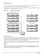
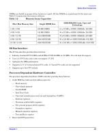
Introduction System Board Components DIMMs are loaded in groups of four, known as a quad. All four DIMMs in a quad must be the same size. Table 1-2 summarizes the memory solutions. Table 1-2 Memory Array Capacities Min / Max Memory Size 1 GB / 3 GB 2 GB / 6 GB 4 GB / 12 GB 8 GB / 24 GB 16 GB / 32 GB Single DIMM Size 256 MB DIMM 512 MB DIMM 1024 MB DIMM 2048 MB DIMM 4096 MB DIMM DDR SDRAM Count, Type and Technology 18 x 32 MB x 4 DDR1 SDRAMs (128 MB) 36 x 32 MB x 4 DDR1 SDRAMs (128 MB) 36 x 64 MB x 4 DDR1 SDRAMs (256 MB) 36 x 128 MB x 4 DDR1 SDRAMs (512 MB) 36 x 256 MB x 4 DDR1 SDRAMs (1024 MB) I/O Bus Interface The I/O bus interface provides these features: • Industry standard PCI 33 MHz and 66 MHz, PCI-X 66 MHz to 133 MHz, 32 or 64 data bit support • Uses 3.3 V PCI only, and it does not support 5 V PCI • Optimizes for DMA performance • Supports 3.3 V or Universal keyed PCI cards. 5 V keyed PCI cards are not supported • Supports up to four PCI sockets Processor Dependent Hardware Controller The processor dependent hardware (PDH) controller provides these features: • 16-bit PDH bus with reserved address space for: - Flash memory - Non-volatile memory - Scratch RAM - Real Time Clock - Universal asynchronous receivers and transmitters (UARTs) - External registers - Firmware read/writable registers - Two general purpose 32-bit registers - Semaphore registers - Monarch selection registers - Test and Reset register • Reset and INIT generation Chapter 1 23
-
 1
1 -
2
-
3
-
4
-
5
-
6
-
7
-
8
-
9
-
10
-
11
-
12
-
13
-
14
-
15
-
16
-
17
-
 18
18 -
 19
19 -
 20
20 -
 21
21 -
 22
22 -
 23
23 -
 24
24 -
 25
25 -
 26
26 -
 27
27 -
 28
28 -
29
-
30
-
31
-
32
-
33
-
34
-
35
-
36
-
37
-
38
-
39
-
40
-
41
-
42
-
43
-
44
-
45
-
46
-
47
-
48
-
49
-
50
-
51
-
52
-
53
-
54
-
55
-
56
-
57
-
58
-
59
-
60
-
61
-
62
-
63
-
64
-
65
-
66
-
67
-
68
-
69
-
70
-
71
-
72
-
73
-
74
-
75
-
76
-
77
-
78
-
79
-
80
-
81
-
82
-
83
-
84
-
85
-
86
-
87
-
88
-
89
-
90
-
91
-
92
-
93
-
94
-
95
-
96
-
97
-
98
-
99
-
100
-
101
-
102
-
103
-
104
-
105
-
106
-
107
-
108
-
109
 |
 |
