HP Integrity rx2620 Installation Guide, Third Edition - HP Integrity rx2620 (A - Page 51
Removing the Processor Airflow Guide
 |
View all HP Integrity rx2620 manuals
Add to My Manuals
Save this manual to your list of manuals |
Page 51 highlights
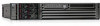
Installing Additional Components Installing an Additional Processor c. At the same time, grasp the back end of the airflow guide and lift the guide out of the system. Figure 3-19 Removing the Processor Airflow Guide Front of server Step 9. Unlock the zero insertion force (ZIF) socket processor locking mechanism using the special processor tool (P/N 5069-5441) or equivalent 2.5 mm hex tool. Insert the tool into the lock and rotate the special processor tool 180 degrees counterclockwise. Verify that the processor-locking mechanism is rotated into the unlocked position. Figure 3-20 shows how to unlock the ZIF socket. CAUTION The ZIF socket for the processor is locked and unlocked by 1/2 of a full turn of the 2.5 mm hex tool. The counterclockwise 180 degree rotation (1/2 turn) unlocks the socket. A clockwise 180 degree rotation locks the socket. Attempting to turn the locking mechanism more that 180 degrees will severely damage the socket. Figure 3-20 Unlocking the Processor Module Locking Mechanism CPU 1 slot (empty) Front of server Chapter 3 51
-
 1
1 -
2
-
3
-
4
-
5
-
6
-
7
-
8
-
9
-
10
-
11
-
12
-
13
-
14
-
15
-
16
-
17
-
18
-
19
-
20
-
21
-
22
-
23
-
24
-
25
-
26
-
27
-
28
-
29
-
30
-
31
-
32
-
33
-
34
-
35
-
36
-
37
-
38
-
39
-
40
-
41
-
42
-
43
-
44
-
45
-
 46
46 -
 47
47 -
 48
48 -
 49
49 -
 50
50 -
 51
51 -
 52
52 -
 53
53 -
 54
54 -
 55
55 -
 56
56 -
57
-
58
-
59
-
60
-
61
-
62
-
63
-
64
-
65
-
66
-
67
-
68
-
69
-
70
-
71
-
72
-
73
-
74
-
75
-
76
-
77
-
78
-
79
-
80
-
81
-
82
-
83
-
84
-
85
-
86
-
87
-
88
-
89
-
90
-
91
-
92
-
93
-
94
-
95
-
96
-
97
-
98
-
99
-
100
-
101
-
102
-
103
-
104
-
105
-
106
-
107
-
108
-
109
 |
 |
