HP Integrity rx2620 Installation Guide, Third Edition - HP Integrity rx2620 (A - Page 60
LAN, LAN Gb A, 100/1000 LAN, iLO MP 10/100, LAN optional
 |
View all HP Integrity rx2620 manuals
Add to My Manuals
Save this manual to your list of manuals |
Page 60 highlights
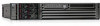
Connecting Cables LAN Step 2. Install the plastic clip through the rectangular slot on the power retention bracket, and pull it through until the clip clicks into place. See Figure 5-2. Figure 5-2 Power Retention Clip and Tie Wrap Step 3. Install the power cord bracket onto the server using the screws you just removed. Step 4. Take the AC cord tie wrap and wrap it around the circumference of the AC cord and through the hole in the tie wrap, near the connector. Step 5. Insert the tie wrap into the plastic clip. See Figure 5-2. Step 6. Repeat steps 2 through 5 (skip step 3) to secure the second power supply power cord (if necessary). LAN The server has two LAN ports that can provide network connectivity. Figure 5-3 shows the available LAN ports for the server. Figure 5-3 Rear Panel LAN Ports WARNING Unplug all power cords from system before servicing PWR 2 PWR 1 iLO MP 10/100 LAN (optional) Management Card LAN 10/100 VGA Automatic Internal SCSI Termination SCSI LVD/SE LAN Gb A LAN Gb A 10/100/1000 LAN MP RESET CONSOLE / REMOTE / UPS TOC LAN Gb B USB LAN Gb B 10/100/1000 LAN CONSOLE SERIAL A SERIAL B To enable general network connectivity for the server, follow these steps: Step 1. Obtain valid IP addresses for each LAN port you plan to activate. Step 2. Connect the LAN cable from an available LAN port into a live connection on the network. 60 Chapter 5
-
 1
1 -
2
-
3
-
4
-
5
-
6
-
7
-
8
-
9
-
10
-
11
-
12
-
13
-
14
-
15
-
16
-
17
-
18
-
19
-
20
-
21
-
22
-
23
-
24
-
25
-
26
-
27
-
28
-
29
-
30
-
31
-
32
-
33
-
34
-
35
-
36
-
37
-
38
-
39
-
40
-
41
-
42
-
43
-
44
-
45
-
46
-
47
-
48
-
49
-
50
-
51
-
52
-
53
-
54
-
 55
55 -
 56
56 -
 57
57 -
 58
58 -
 59
59 -
 60
60 -
 61
61 -
 62
62 -
 63
63 -
 64
64 -
 65
65 -
66
-
67
-
68
-
69
-
70
-
71
-
72
-
73
-
74
-
75
-
76
-
77
-
78
-
79
-
80
-
81
-
82
-
83
-
84
-
85
-
86
-
87
-
88
-
89
-
90
-
91
-
92
-
93
-
94
-
95
-
96
-
97
-
98
-
99
-
100
-
101
-
102
-
103
-
104
-
105
-
106
-
107
-
108
-
109
 |
 |
