HP Integrity rx2620 Installation Guide, Third Edition - HP Integrity rx2620 (A - Page 20
System Board Components, System Block Diagram
 |
View all HP Integrity rx2620 manuals
Add to My Manuals
Save this manual to your list of manuals |
Page 20 highlights
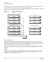
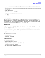
Introduction System Board Components System Board Components This section provides a block diagram of the system board and descriptions of key components (integrated circuits) on the board. Figure 1-4 shows a block diagram of the rx2620 server. Figure 1-4 System Block Diagram Itanium-2 IPF Itanium-2 IPF 267MHz 8.5GB/S Peak Data BandWidth 200MHz 6.4GB/S Peak Data BandWidth PCI-X Interface PCI-X 133 "Slot1" ASIC Bus Interface ROPE 4 ROPE 5 ASIC Bus Interface Industry Standard DDR1 DIMM DIMM DIMM DIMM DIMM DIMM MEMORY DIMM DIMM DIMM DIMM DIMM DIMM 133 MHz bus clock 267 MT/s data rate 8.5GB/s peak data bandwidth DMD ASIC Bus Interface PDH Bus FMW/PDC Flash 816MMBB FMW SRAM (on battery, scratch RAM + NVM) 512KB RTC DUART COM1 COM2 System/BMC Console & Serial Port Serial Port OS Enabled PCI-X 133 "Slot2" ASIC Bus Interface PCI-X 133 "Slot3" ASIC Bus Interface PCI-X 133 "Slot4" ASIC Bus Interface ROPE 3 ROPE 2 ROPE 6 ROPE 7 VGA Optional VGA Battery• SRAM DRAM Flash etc... PCI 33/32 ASIC Bus Interface RiLMOC/GMSPP UPS Console Modem LAN100BT Management Processor 267MHz 8b data 533MB/s Peak Data Bandwidth per rope FPGA BMC LPC Manageability LPC + ACPI Bus Controller BMC SRAM 512KB BMC (on battery, scratch RAM• bus +NVM+ FPL • forward progress log) BMC FLASH 1MB I2C etc... LED STATUS PANEL LOCATOR DIAG LEDs ON-OFF LAN Activity ROPE 0 ASIC Bus Interface ROPE 1 PCI 33/32 I2C, etc... ASIC Bus Interface PCI-X 133 FLASH LLAANN 1100//11000// 110G00 SCSI ID 2 HDD #3 IDE USB 2.0 To AGP Riser DVD RW Slim Line Keyboard Mouse SCSI ID 1 SCSI ID 0 HDD #2 HDD #1 SCSI BACKPLANE (SE-LVDS SCA-2 80pin) Channel B Channel A SCSI U320 FLASH externEaxlte(rsne-alvlds 68p) (SE-LVDS 68p) The following describes the main components of the system board: • "Processor Sockets" on page 21 • "Processor Bus" on page 21 • "ZX1 I/O and Memory Controller" on page 21 • "System Memory" on page 21 • "I/O Bus Interface" on page 23 • "Processor Dependent Hardware Controller" on page 23 20 Chapter 1
-
 1
1 -
2
-
3
-
4
-
5
-
6
-
7
-
8
-
9
-
10
-
11
-
12
-
13
-
14
-
 15
15 -
 16
16 -
 17
17 -
 18
18 -
 19
19 -
 20
20 -
 21
21 -
 22
22 -
 23
23 -
 24
24 -
 25
25 -
26
-
27
-
28
-
29
-
30
-
31
-
32
-
33
-
34
-
35
-
36
-
37
-
38
-
39
-
40
-
41
-
42
-
43
-
44
-
45
-
46
-
47
-
48
-
49
-
50
-
51
-
52
-
53
-
54
-
55
-
56
-
57
-
58
-
59
-
60
-
61
-
62
-
63
-
64
-
65
-
66
-
67
-
68
-
69
-
70
-
71
-
72
-
73
-
74
-
75
-
76
-
77
-
78
-
79
-
80
-
81
-
82
-
83
-
84
-
85
-
86
-
87
-
88
-
89
-
90
-
91
-
92
-
93
-
94
-
95
-
96
-
97
-
98
-
99
-
100
-
101
-
102
-
103
-
104
-
105
-
106
-
107
-
108
-
109
 |
 |
