HP Integrity rx2620 Installation Guide, Third Edition - HP Integrity rx2620 (A - Page 50
Processor Location on System Board, Step 7.
 |
View all HP Integrity rx2620 manuals
Add to My Manuals
Save this manual to your list of manuals |
Page 50 highlights
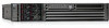
Installing Additional Components Installing an Additional Processor Figure 3-18 Processor Location on System Board CPU 0 slot CPU 1 slot Front of server CAUTION Ensure that the cache size is identical for all processors. Failure to observe this caution will result in system failure. Ensure that all processors are rated for use at the same speed. Failure to observe this caution will result in performance degradation. Valid processors are identified in the Parts Information chapter of the HP Integrity rx2620 Maintenance Guide. Step 7. Remove the top metal cover if not already removed. See "Removing the Top Metal Cover" on page 35. Step 8. Remove the processor airflow guide. Figure 3-19 shows how to remove the processor airflow guide. a. Remove the IDE cable and power module cables from the processor airflow guide cable clips. CAUTION Record the cable routing of these cables to ensure the cables are returned to their correct routes. b. Hold the guide using the opening on top of the guide. 50 Chapter 3
-
 1
1 -
2
-
3
-
4
-
5
-
6
-
7
-
8
-
9
-
10
-
11
-
12
-
13
-
14
-
15
-
16
-
17
-
18
-
19
-
20
-
21
-
22
-
23
-
24
-
25
-
26
-
27
-
28
-
29
-
30
-
31
-
32
-
33
-
34
-
35
-
36
-
37
-
38
-
39
-
40
-
41
-
42
-
43
-
44
-
 45
45 -
 46
46 -
 47
47 -
 48
48 -
 49
49 -
 50
50 -
 51
51 -
 52
52 -
 53
53 -
 54
54 -
 55
55 -
56
-
57
-
58
-
59
-
60
-
61
-
62
-
63
-
64
-
65
-
66
-
67
-
68
-
69
-
70
-
71
-
72
-
73
-
74
-
75
-
76
-
77
-
78
-
79
-
80
-
81
-
82
-
83
-
84
-
85
-
86
-
87
-
88
-
89
-
90
-
91
-
92
-
93
-
94
-
95
-
96
-
97
-
98
-
99
-
100
-
101
-
102
-
103
-
104
-
105
-
106
-
107
-
108
-
109
 |
 |
